EasyManuals Logo

Connective Peripherals ES-U Series User Manual

Connective Peripherals ES-U Series
53 pages
To Next Page IconTo Next Page
To Previous Page IconTo Previous Page
Page #33 background imageLoading...
Page #33 background image
USB to Serial Converters Manual
Version 2.0
Document Reference No.: CP_000032 Clearance No.: CP#022
Copyright © Connective Peripherals Pte Ltd 33
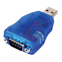
RS232 Pin-Out (ES-U-2101-MB)
The ES-U-2101-MB has a reduced set of signals which are shown in the table below. It includes the most
commonly used signals TxD/RxD/RTS/CTS/Gnd.
Note that the other pins of the connector must be left unconnected as indicated below.
Pin Number
Pin Type
Description
1
Leave un-connected
2
Input
RXD = Receive Data
3
Output
TXD = Transmit Data
4
Leave un-connected
5
Ground
GND = RS232 signal ground
6
Leave un-connected
7
Output
RTS = Request To Send
8
Input
CTS = Clear To Send
9
Leave un-connected
Table 12 - RS-232 Pin-Out for DB-9 connector on ES-U-2101-MB
RJ45 connector
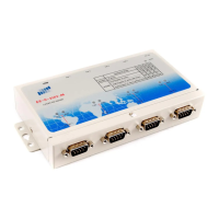
The table below shows the pin-out of the RJ45 connectors used on the ES-U-1032-RM converter.
This converter is also provided with adapter cables which convert the RJ45 into a DB-9 connector. This
connector uses the same pin-out as in Table 11 above but the Ring Indicator signal is not available as it is
not brought out on the RJ45 connector.
Figure 23 -RJ45 Connector Pin Numbers
Pin Number
Pin Type
Description
1
Output
RTS = Request To Send
2
Output
DTR = Data Terminal Ready
3
Ground
GND = RS232 signal ground
1 2 3 4 5 6 7 8

Table of Contents

Questions and Answers:

Question and Answer IconNeed help?

Do you have a question about the Connective Peripherals ES-U Series and is the answer not in the manual?

Connective Peripherals ES-U Series Specifications

General IconGeneral
BrandConnective Peripherals
ModelES-U Series
CategoryMedia Converter
LanguageEnglish

Related product manuals