Adjustme
1f
the
:
~
lifter
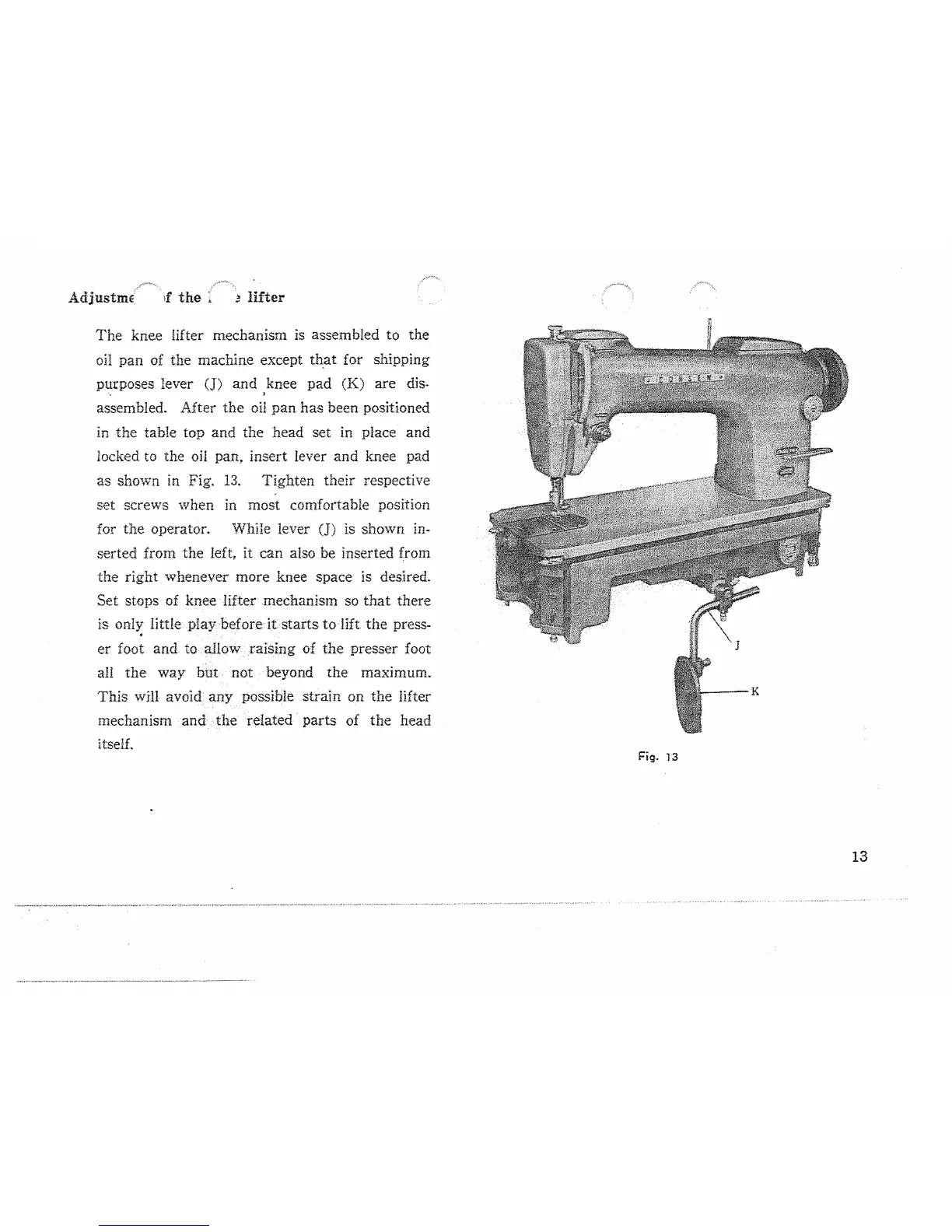
The
knee lifter mechanism is assembled to the
oil pan of the machine except th,at for shipping
purposes lever
(J)
and
knee
pad
(K)
are dis.
·,
'
assembled. After
the
oH
pan
has been positioned
in
the table top and the head set in place and
locked to the
oil
pan, insert lever
and
knee pad
as shown in Fig.
13.
Tighten their respective
set screws when in most comfortable position
for the
operator. While lever (J) is shown
in-
serted from the left, it can also be inserted from
the right whenever more knee space is desired.
Set stops of knee lifter mechanism
so
that
there
is only little play before
it
starts
to
lift
the press-
•
er foot
and
to
a.How
raising of the presser foot
aH
the
way
but
not beyond
the
maximum.
This
wm
avoid
any
possible strain on
the
lifter
mechanism and
the
related
parts
of the head
itself.
Fig. 13
13