Commander S100 Step by Step Guide 2
English
Introduction
This guide provides step-by-step instructions on how to mount the drive, wire the drive using appropriate fuses and
cables, program the drive and run the motor. The Commander S100 is fully compatible with the mobile app, Marshal,
which can be found on Google Play and the App Store, or alongside the full Commander S100 User Guide at
'www.drive-setup.com'.
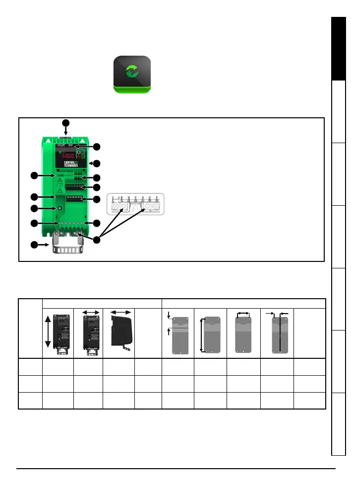
Features of the drive
Figure 1-1 Feature diagram
STEP 1: Mount the drive
A drill template for wall mounting is included on the drive packaging for quick installation.
Table 1-1 Drive dimensions
Drives can be panel mounted with 0 mm space between them. A minimum clearance of 45 mm (1.77 in) is required
above and below the drive except for frame size 1 drives with a power rating ≤0.55 kW. For these drives, a minimum
clearance of 100 mm (3.94 in) is required above and below the drive.
The drive should be mounted in an ambient temperature range of 0 °C to 60 °C (32 °F to 140 °F). If the drive needs to
be mounted with reduced clearances, or in an ambient temperature > 40 °C
(104 °F), the drive must be derated. Refer to the Technical Data section in the Commander S100 User Guide for
derating information.
Frame
size
Overall Dimensions (±0.5 mm) Mounting Dimensions (±0.5 mm)
Weight
Ø
Maximum
Diameter
1
156 mm
6.14 in
68 mm
2.70 in
130 mm
5.12 in
0.6 kg
1.2 lb
40 mm
1.56 in
145 mm
5.71 in
45 mm
1.77 in
22 mm
0.89 in
4.8 mm
0.19 in
2
192 mm
7.56 in
68 mm
2.70 in
132 mm
5.20 in
0.7 kg
1.5 lb
40 mm
1.56 in
180 mm
7.11 in
45 mm
1.77 in
22 mm
0.89 in
4.8 mm
0.19 in
3
192 mm
7.56 in
90 mm
3.54 in
132 mm
5.20 in
0.7 kg
1.5 lb
40 mm
1.56 in
180 mm
7.11 in
65 mm
2.56 in
37 mm
1.48 in
4.8 mm
0.19 in
MARSHAL
• NFC powerless data transfer
• First time setup and commissioning
• Diagnostics and monitoring
1. Din Rail Release Clip
2. NFC Reader Location
3. Identification Information
4. Rating Information (side of drive)*
5. Relay Connections
6. Digital IO Connections
7. EIA 485 Communications Port
8. Analog IO Connections
9. EMC Filter Disconnect Screw **
10. AC Supply Connections
11. Motor Connections
12. Ground / Protective Earth Connections
13. Cable Screening Bracket
*Always check the drive voltage rating is suitable for
the installation
**Read information in the User Guide before removal