3 Commander S100 Step by Step Guide
STEP 2: Wire the drive
Power Connections
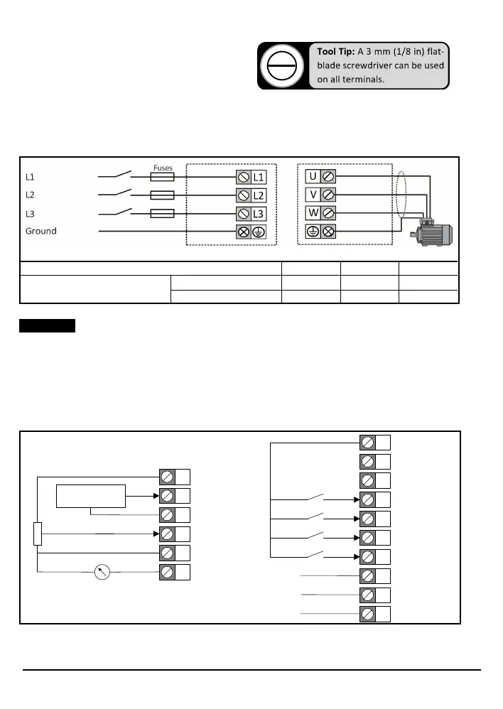
Connect the supply and motor connections using the cables and fuses or MCB's quoted in the table 1-2. When using a
single-phase supply, the supply should be connected to L1 and L2.
Figure 1-2 Power terminal connection
To meet UL requirements, UL Listed closed-loop connectors sized according to the field wiring must be used for
ground connections.
Ground connections
Ground conductor size:- Either 10 mm² or two conductors of the same cross-sectional area as the input conductors.
For location of ground connection refer to Figure 1-1.
Control connections
Figure 1-3 Helium control terminal connections (Default Configurations)
For other IO configurations see Control Connections section in the User Guide or use Marshal.
Drive Voltage Rating 110 V 230 V 400 V
Recommended Torque Setting
Power Connections 0.5 Nm 0.5 Nm 0.6 Nm
Ground Connections 1.5 Nm 1.5 Nm 1.5 Nm
1
2
3
4
5
6
+10 V Output
4-20 mA Input...
0-10 V Input...
0 V
0 V
Analog Output
Remote Reference
10k
Local Reference
9
10
11
12
13
14
+24 V Output
0 V
Enable...
No Default Funciton...
Run Forward...
Run Reverse...
15 Reference Select...
41
42
43
Relay Normally Open
Relay Common
Relay Normally Closed
Drive Healthy
Drive Unhealthy
Ramp Output