Commander SE User Guide 18
Issue Number 8 www.controltechniques.com
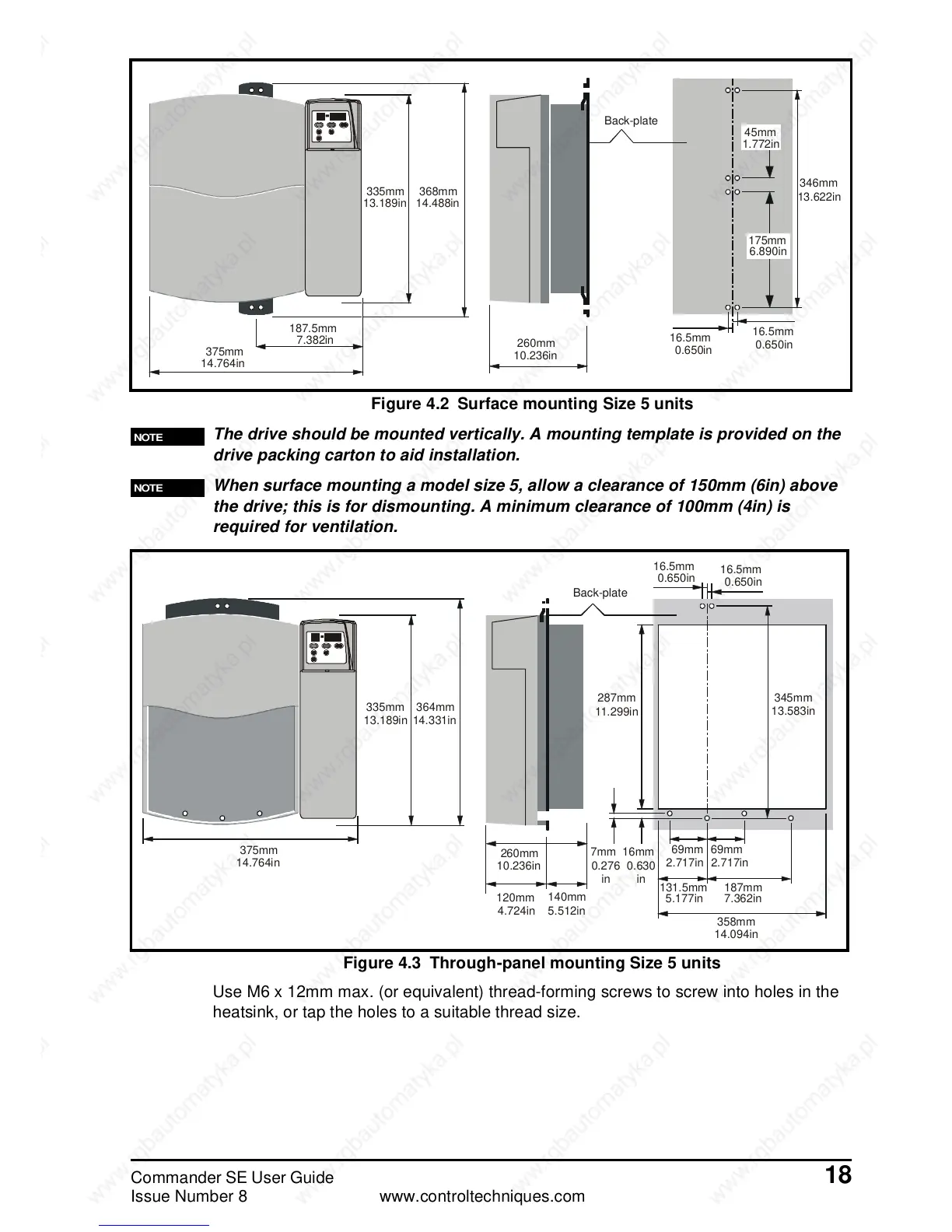
Figure 4.2 Surface mounting Size 5 units
The drive should be mounted vertically. A mounting template is provided on the
drive packing carton to aid installation.
When surface mounting a model size 5, allow a clearance of 150mm (6in) above
the drive; this is for dismounting. A minimum clearance of 100mm (4in) is
required for ventilation.
Figure 4.3 Through-panel mounting Size 5 units
Use M6 x 12mm max. (or equivalent) thread-forming screws to screw into holes in the
heatsink, or tap the holes to a suitable thread size.
NOTE
Back-plate
13.189in 14.488in
1.772in
13.622in
6.890in
0.650in
0.650in
10.236in
7.382in
14.764in
375mm
187.5mm
335mm 368mm
260mm
16.5mm
16.5mm
346mm
175mm
45mm
NOTE
Back-plate
13.583in
0.650in
0.650in
11.299in
13.189in 14.331in
14.764in
10.236in
4.724in 5.512in
2.717in2.717in
5.177in 7.362in
14.094in
0.276
in
0.630
in
375mm
335mm 364mm
120mm
140mm
260mm
7mm 16mm
287mm
 Loading...
