35 Commander SE User Guide
www.controltechniques.com Issue Number 8
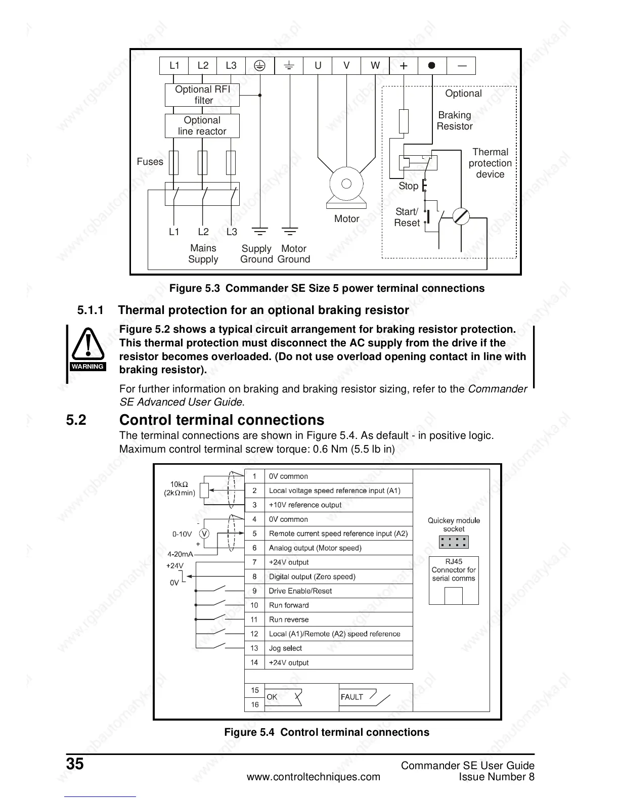
Figure 5.3 Commander SE Size 5 power terminal connections
5.1.1 Thermal protection for an optional braking resistor
Figure 5.2 shows a typical circuit arrangement for braking resistor protection.
This thermal protection must disconnect the AC supply from the drive if the
resistor becomes overloaded. (Do not use overload opening contact in line with
braking resistor).
For further information on braking and braking resistor sizing, refer to the Commander
SE Advanced User Guide.
5.2 Control terminal connections
The terminal connections are shown in Figure 5.4. As default - in positive logic.
Maximum control terminal screw torque: 0.6 Nm (5.5 lb in)
Figure 5.4 Control terminal connections
L1 L2
L2
L1
+
_
L3 U V W
Optional RFI
filter
Optional
line reactor
Fuses
L3
Mains
Supply
Motor
Motor
Ground
Start/
Reset
Stop
 Loading...
