Commander SE User Guide 34
Issue Number 8 www.controltechniques.com
5 Terminals
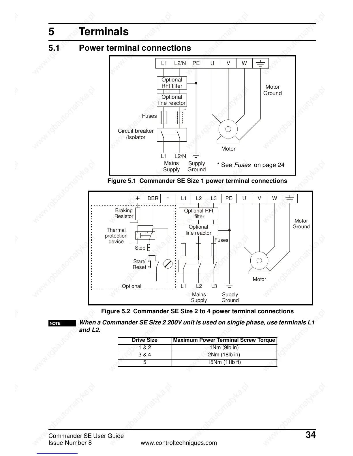
5.1 Power terminal connections
Figure 5.1 Commander SE Size 1 power terminal connections
Figure 5.2 Commander SE Size 2 to 4 power terminal connections
When a Commander SE Size 2 200V unit is used on single phase, use terminals L1
and L2.
L1 L2/N PE U V W
Optional
RFI filter
Optional
line reactor
Mains
Supply
Fuses
L1 L2/N
Supply
Ground
Motor
Motor
Ground
Circuit breaker
/Isolator
*
*SeeFuses on page 24
L1 L2
L2
L1
+
-
L3 PEDBR U V W
Optional RFI
filter
Optional
line reactor
Fuses
L3
Supply
Ground
Mains
Supply
Motor
Motor
Ground
Start/
Reset
Stop
Optional
Thermal
protection
device
Braking
Resistor
NOTE
Drive Size Maximum Power Terminal Screw Torque
1&2 1Nm(9lbin)
3 & 4 2Nm (18lb in)
5 15Nm (11lb ft)
 Loading...
