37 Commander SE User Guide
www.controltechniques.com Issue Number 8
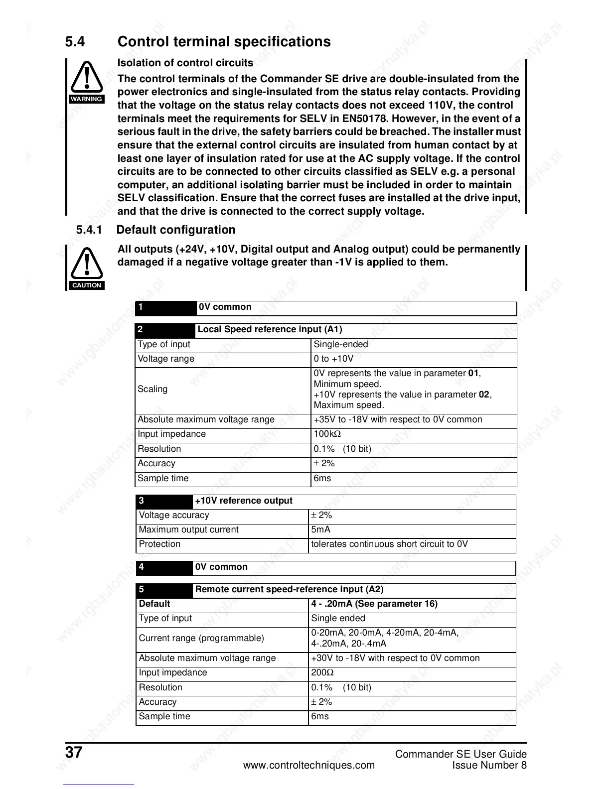
5.4 Control terminal specifications
Isolation of control circuits
The control terminals of the Commander SE drive are double-insulated from the
power electronics and single-insulated from the status relay contacts. Providing
that the voltage on the status relay contacts does not exceed 110V, the control
terminals meet the requirements for SELV in EN50178. However, in the event of a
serious fault in the drive, the safety barriers could be breached. The installer must
ensure that the external control circuits are insulated from human contact by at
least one layer of insulation rated for use at the AC supply voltage. If the control
circuits are to be connected to other circuits classified as SELV e.g. a personal
computer, an additional isolating barrier must be included in order to maintain
SELV classification. Ensure that the correct fuses are installed at the drive input,
and that the drive is connected to the correct supply voltage.
5.4.1 Default configuration
All outputs (+24V, +10V, Digital output and Analog output) could be permanently
damaged if a negative voltage greater than -1V is applied to them.
WARNING
CAUTION
1 0V common
2 Local Speed reference input (A1)
Type of input Single-ended
Voltage range 0 to +10V
Scaling
0V represents the value in parameter 01,
Minimum speed.
+10V represents the value in parameter 02,
Maximum speed.
Absolute maximum voltage range +35V to -18V with respect to 0V common
Input impedance 100kΩ
Resolution 0.1% (10 bit)
Accuracy ± 2%
Sample time 6ms
3 +10V reference output
Voltage accuracy ± 2%
Maximum output current 5mA
Protection tolerates continuous short circuit to 0V
4 0V common
5 Remote current speed-reference input (A2)
Default 4 - .20mA (See parameter 16)
Type of input Single ended
Current range (programmable)
0-20mA, 20-0mA, 4-20mA, 20-4mA,
4-.20mA, 20-.4mA
Absolute maximum voltage range +30V to -18V with respect to 0V common
Input impedance 200Ω
Resolution 0.1% (10 bit)
Accuracy ± 2%
Sample time 6ms
 Loading...
