Commander SE User Guide 60
Issue Number 8 www.controltechniques.com
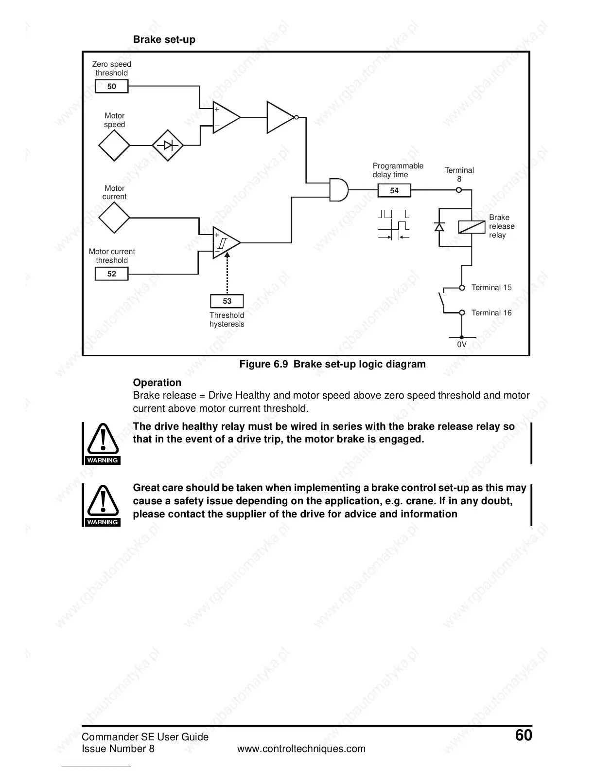
Brake set-up
Figure 6.9 Brake set-up logic diagram
Operation
Brake release = Drive Healthy and motor speed above zero speed threshold and motor
current above motor current threshold.
The drive healthy relay must be wired in series with the brake release relay so
that in the event of a drive trip, the motor brake is engaged.
Great care should be taken when implementing a brake control set-up as this may
cause a safety issue depending on the application, e.g. crane. If in any doubt,
please contact the supplier of the drive for advice and information
50
Zero speed
threshold
Motor
speed
Motor
current
52
Motor current
threshold
+
_
+
_
53
Threshold
hysteresis
54
Programmable
delay time
Terminal
8
Brake
release
relay
0V
Terminal 15
Terminal 16
WARNING
WARNING
 Loading...
