*
31 M’Ax Advanced User Guide
www.controltechniques.com Issue Number: 4
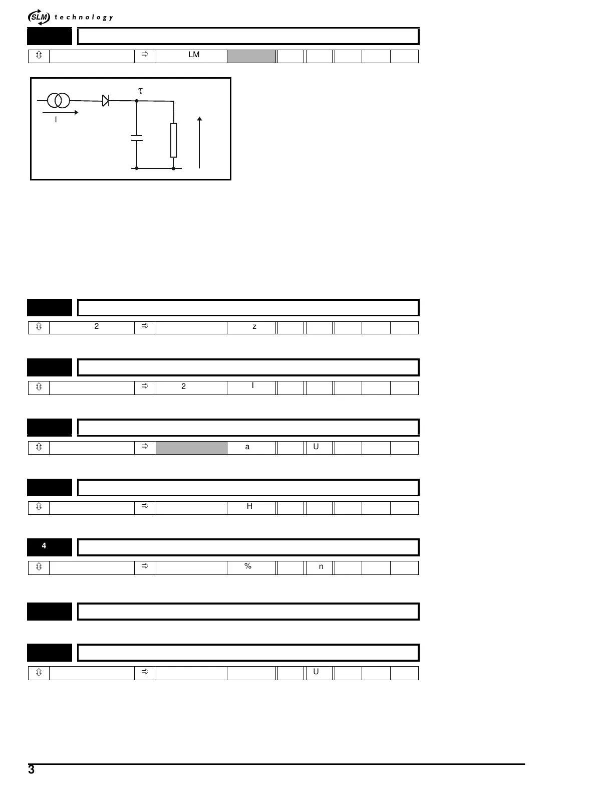
The motor is modelled thermally in a way that is equivalent to the electrical circuit shown below.
The temperature of the motor as a percentage of maximum temperature, with a constant current magnitude of I, after time t is given by
Temp =[I
2
/(Motor rated current x Motor overload threshold)
2
](1 - e-t/τ)x100%
This assumes that the maximum allowed motor temperature is produced with 110% rated current and that τ is the thermal time constant of the
point in the motor that reaches it maximum allowed temperature first. τ is defined by SLM (indicated by parameter [4.15]) and Motor overload
threshold is defined in parameter [4.52]. When the estimated temperature reaches Motor overload threshold the drive limits the current to
current scaling set by the parameter [4.53]. The time for a trip or reduction of current limit from cold with constant motor current is given by:
T
trip
=-(Par 4.15)xln(1 -((4.52/100)xPar 5.07 / Par 4.01)
2
)
The thermal model accumulator is set to zero at power-up and accumulates the temperature of the motor whilst the drive remains powered-
up.
Refer to parameter 4.12.
Refer to parameter 4.07 and P.I.D calculation section in Menu 3.
Not available in current software version.
Refer to parameter 4.12.
Refer to parameter 4.07 and P.I.D calculation section in Menu 3.
For drive’s internal system purposes only.
See parameter 4.15.Toactivateanewvalueasaveandpowerdownisnecessary.
4.15 Motor-thermal time-constant
ôð
SLM RO Uni 0.16
4.23 Current-demand filter 2 cut-off frequency
ô
0 ~ 1200
ð
500 Hz RW Uni
4.24 Symmetrical current limit Kc2
ô
0~300
ð
200.0
%I
M
RW Uni
4.26 Torque-compensation gain
ô
0 ~ 5000
ð
Rads/s RW Uni
4.27 Current-demand filter 3 cut-off frequency
ô
0 ~ 1200
ð
500 Hz RW Uni
4.28 Symmetrical current limit Kc3
ô
0~300
ð
200.00
%I
M
RW Uni
4.51 Reserved for internal system purposes
4.52 Motor thermal-overload trip level
ô
0~125
ð
110
%I
M
RW Uni
=RC
I
2
C
R
Te mp