Safety
Information
Product
Information
Mechanical
Installation
Electrical
Installation
Getting
Started
Menu 0
Running
the motor
Optimisation Macros
Advanced
Parameters
Technical
Data
Diagnostics
UL Listing
Information
Unidrive User Guide 99
Issue Number: 9 www.controltechniques.com
Open loop
The above equation gives a value less than 150% if Pr 5.10 >0.93. The
maximum current limit value used by the drive is 150% if the calculated
value is less than 150%.
Closed loop vector
Servo
Unidrive VTC
8.3 Motor thermal protection
The Unidrive models the temperature of the motor using the motor rated
current parameter, the thermal time constant parameter and the actual
current flowing at any point in time.
An accumulator (Pr 4.19) increments or decrements based on the
current flowing in the motor.
If the motor runs for a given time at a level below the rated current of the
motor the accumulator will settle at a value equivalent to the motor
temperature.
An it.ac trip instantaneously occurs if the accumulator reaches 100%.
This can only occur if the rms current flowing is greater than 105%. or if
a current peak lasts for enough time to cause the accumulator to peak at
or above this level.
The default setting of the thermal time constant (Pr 4.15) is 89s for an
induction motor (open loop and closed loop vector) which is equivalent
to an overload of 150% for 60s from cold.
The default value for a servo motor is 7s which is equivalent to an
overload of 175% for 4s from cold.
The maximum value for the thermal time constant can be increased up
to a maximum value of 400s to allow an increased overload if the motor
thermal characteristics permit.
For applications using CT Dynamics Unimotors the thermal time
constants can be found in the Unimotor manual.
8.4 Switching frequency
The default switching frequency for the drive is 3kHz however this can
be increased up to a maximum value of 12kHz.
If the switching frequency is increased the following apply:
1. Increased heat loss in the drive which means that derating to the
output current must be applied.
See the derating table for switching frequency and ambient
temperature in the Chapter 11 Technical Data on page 190.
2. Reduced heating of the motor - due to improved output waveform
quality
3. Increased sample rate on the speed and current controllers
A trade off must be made between motor heating and drive heating and
the demands of the application with respect to the sample time required.
8.5 High speed operation
8.5.1 Encoder feedback limits
In the closed loop modes when using encoder feedback the maximum
speed of the drive is limited by the maximum frequency limit of the
encoder input as follows:
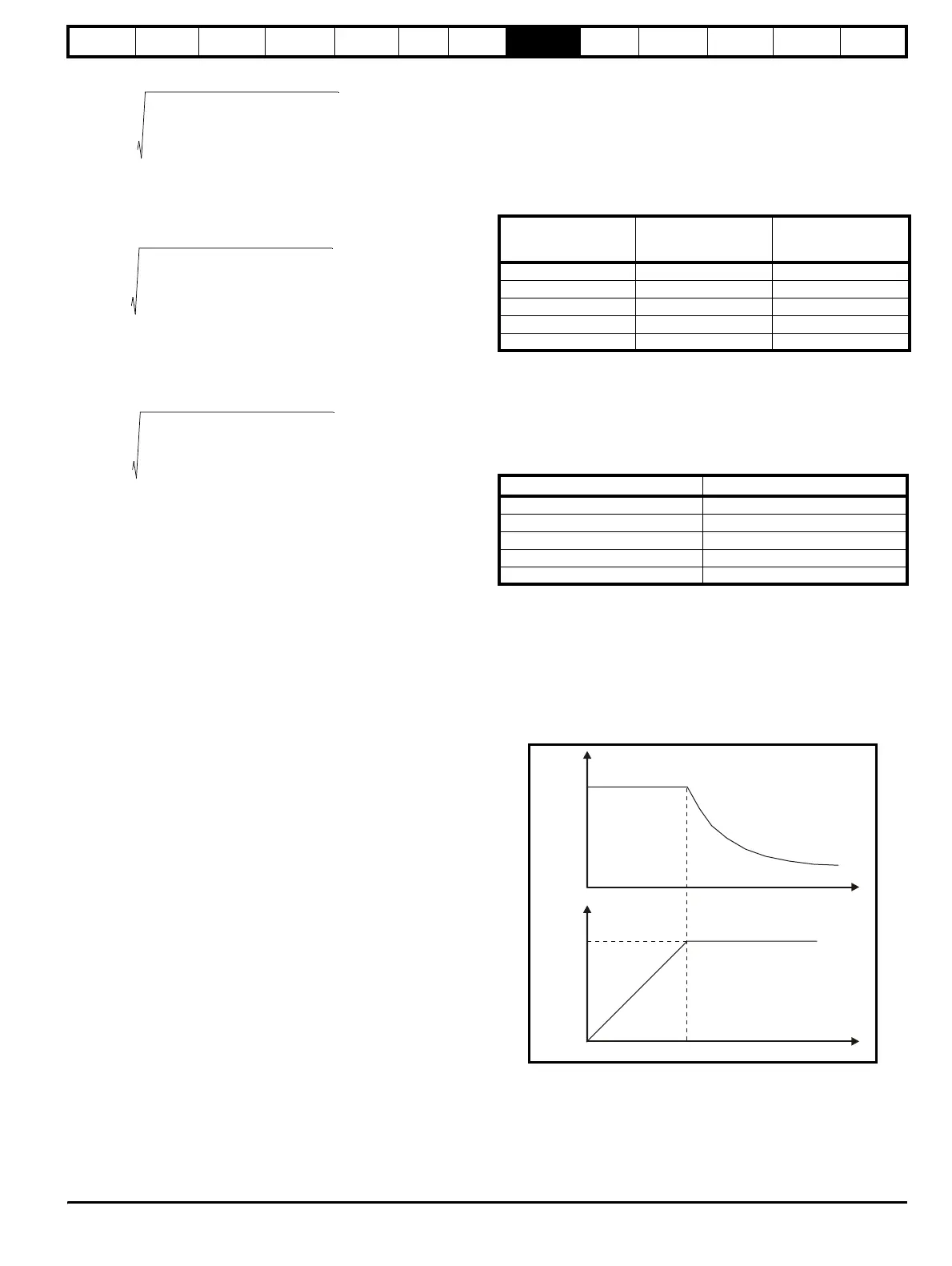
8.5.2 Field weakening (constant power) operation
(Open loop and closed loop vector mode only)
The Unidrive can be used to run an induction machine above
synchronous speed into the constant power region. The speed
continues to increase and the available shaft torque reduces.
The characteristics below show the torque and output voltage
characteristics as the speed is increased above the rated value.
Care must be taken to ensure the torque available above base speed is
sufficient for the application to run satisfactorily.
I
MAX
%
1.597
2
Pr 11.32
Pr 5.07
-----------------------
2
1–×
Pr 5.10
2
----------------------------------------------------------------------
1+
0.156 Pr 11.32×
Pr 5.10 Pr 5.07×
---------------------------------------------
–
100×=
I
MAX
%
1.597
2
Pr 11.32
Pr 5.07
-----------------------
2
1–×
Pr 5.10
2
----------------------------------------------------------------------
1+
100×=
I
MAX
%1.767
Pr 11.32
Pr 5.07
-----------------------
×
100×=
I
MAX
%
1.203
2
Pr 11.32
Pr 5.07
-----------------------
2
1–×
Pr 5.10
2
----------------------------------------------------------------------
1+
100×=
Switching frequency
Sample time (
µs)
OL >Current control
CL > Speed control
Sample time (µs)
OL > Peak limit
CL > Current control
3 333 333
4.5 444 222
6 333 166
9444222
12 333 166
Encoder PPR Maximum Speed (rpm)
up to 5,000 3,000
up to 2,500 6,000
up to 1,250 12,000
up to 625 24,000
up to 312 30,000
Rated
voltage
Torque
Speed
S
eed