2-79
1010PVNFM-3A
Section 2
Pressing the <+> or <-> keys will cause the Tn marker to move later or earlier, respectively.
As you adjust the Tn marker, both Tn and Vs (liquid sound velocity) will change accordingly.
To exit this mode, press the <0> key on the keypad.
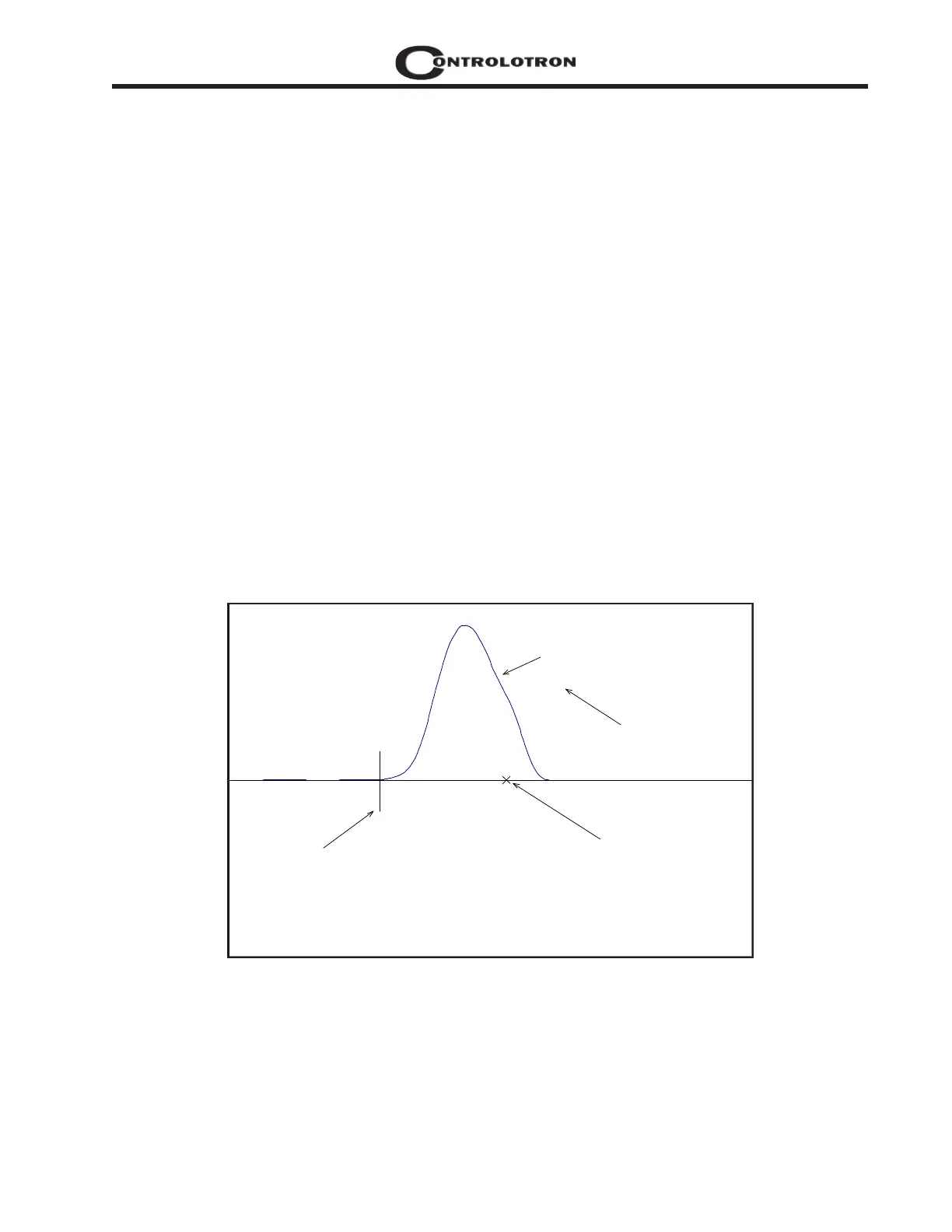
Zero Crossover Adjustment: (Hot Key 4)
Observe the small “X” mark located on the zero crossing line near the middle of the receive
signal in the Graph Screen above. This “X” indicates the central crossover which the 1010 is
using to measure the transit-time delta. This crossover will generally be close to the peak of
the receive signal with at least one well formed (non-aberrated) receive cycle on each side of
the crossover. If it appears that the placement of this crossover is unsatisfactory then it can be
adjusted by pressing the <4> key on the keypad, which will invoke the [ZCOSet] command.
The crossover point can then be moved in either direction on the waveform using the <+> or <-
> keys. The change from the default value (in receive cycles) will appear in the number to the
right of the command. To exit this mode, press the <0> key.
Envelope Threshold Adjustment: (Hot Key 5 & 6)
Pressing the <=> key causes the graph to toggle between the default signal waveform screen
and the signal envelope screen (see example below). This envelope screen can aid in the diag-
nosis of Tn errors caused by unusual receive waveform distortion. Signal distortion is some-
times caused by poor transducer selection or poor pipe wall conditions, which may result in
an incorrectly measured fluid sound velocity. To improve the automatic measurement of Tn,
the envelope threshold limit can be adjusted to exclude portions of the envelope, which may
be causing the Tn detection problem.
If it appears that the default placement of the Tn marker is incorrect or unstable, it can be
adjusted by pressing the <5> key on the keypad to invoke the [EnvSet] command (while view-
ing the envelope screen). A horizontal line representing the envelope threshold level will
appear along with a number indicating the percentage level. The High and Low thresholds
can then be moved either up or down on the envelope using the <+> or <-> keys. While viewing
the Tn marker position, adjust the thresholds so that they are well above the baseline “noise”
level but below the first major peak. To exit this mode, press the <0> key.
HiSet
F 0.73
VS 1469.73
[ ] 1691:1929 476
D 4:4 4
Tn 55.06 55.06
dT 3.11
S 72 1
SN 124:1
CQ 17:1
Envelope Signal
TN marker
Crossover Marker
Command Line appears here
Envelope Threshold
91
3
HiSet