EasyManua.ls Logo

Controlotron 1010PVDN User Manual

Default Icon
203 pages
To Next Page IconTo Next Page
Page #1 background imageLoading...
Page #1 background image
1 0 1 0 P V N F M - 3 A
SYSTEM 1010PVN/PVDN
NEMA CLAMP-ON
MULTI-FUNCTION FLOWMETER
Made in the USA
FIELD MANUAL
Астана +7(77172)727-132 Волгоград (844)278-03-48 Воронеж (473)204-51-73 Екатеринбург (343)384-55-89
Казань (843)206-01-48 Краснодар (861)203-40-90 Красноярск (391)204-63-61 Москва (495)268-04-70
Нижний Новгород (831)429-08-12 Новосибирск (383)227-86-73 Ростов-на-Дону (863)308-18-15
Самара (846)206-03-16 Санкт-Петербург (812)309-46-40 Саратов (845)249-38 Уфа (347)229-48-12
Россия, Казахстан и другие страны ТС доставка в любой город
единый адрес для всех регионов: ctn@nt-rt.ru
www.controlotron.nt-rt.ru

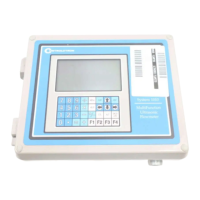
Table of Contents

Questions and Answers:

Controlotron 1010PVDN Specifications

General IconGeneral
CategoryMeasuring Instruments
TypeUltrasonic Flow Meter
Measurement PrincipleTransit-time
Measurement Range±12 m/s
Operating Temperature-20°C to +60°C
Output4-20 mA, Relay
Housing MaterialAluminum

Summary

CONTROLOTRON WARRANTY APPLIES TO SYSTEM 1010

ERRATA

Digital Pgen Function and Wiring Procedure Update

Provides updates on PGEN function and wiring for specific models.

PGEN Wiring Diagram

FOR POSITIVE FLOW / FOR NEGATIVE FLOW

MANUAL ADDENDUM

SETUP PROCEDURE FOR WET-FLOW CALIBRATED 1010 SYSTEMS

Details the setup procedure for wet-flow calibrated 1010 systems.

SETUP PROCEDURE FOR “WET-FLOW CALIBRATED” 1010 SYSTEM

2.1 Transducer Installation

Steps for installing transducers according to diagnostic data.

2.2 Flowmeter Setup

3. TRANSFER INSTALL FUNCTION

3.1 Transfer Install Procedure

Procedure to reposition transducers while maintaining calibration parameters.

EXPANDED I/O OPTION

1010N-2 I/O Module

EXPANDED I/O MODULE OPTION PROGRAMMING

Section 1: 1. GETTING STARTED

1.2 Important Safety Considerations

Critical safety precautions for installation and operation.

Section 2: 2. The 1010PVN Installation Menu

2.2 The Pipe Data Menu

Menu for defining application's pipe parameters.

2.4 The Pick/Install XDCR (Transducer) Menu

2.4.1 How To Select A Transducer Model

Steps to define the type of transducer for the application.

2.4.8 How To Use [Install Completed?]

Procedure to inform the flow computer that transducer mounting is complete.

2.10 The I/O Data Control Menu

2.11.7 Troubleshooting Tips

Flow Computer Messages

List of flow computer messages and recommended actions for troubleshooting.

Section 3: 3. HARDWARE INSTALLATION GUIDE

3.1 Preparing To Mount The Transducers

Steps to prepare for mounting the transducers.

Section 4: 4. The Meter Facilities Menu And Graphic Display SCREENS

4.4 The Datalogger Control Menu

4.5 The Memory Control Menu

4.6 THE RTD CALIBRATE MENU (optional)

4.8 RS-232 SETUP

5.3 Pipe Considerations For Clamp-On Transducer

5.3.3 Flow Velocity Range

Related product manuals