Manual Addendum
1010FMA-14
1
EXPANDED I/O OPTION
(For Systems Equipped With 1010N-7 Modules)
INT R O D UCTI O N
The 1010N-2 I/O Module and 1010N-7 Expanded I/O Module both provide current (Io1, Io2),
voltage (V01 and Vo2) and pulse rate (Pgen 1 and Pgen 2) analog outputs. The Expanded I/O
Module Option allows users to drive as many as four additional 4-20 mA loop-powered instru-
mentation outputs. The following information is intended to be used with the I/O Data Con-
trol and Span Data sections and Analog Output Trim Menu in the field manual.
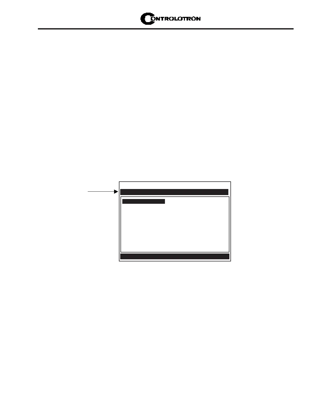
The System 1010 flowmeter provides an Analog Output Setup menu (see below) that allows
the user to assign data functions for these output signals (refer to Analog Output Setup in the
appropriate 1010 field manual). In addition, refer to Installation Drawings 1010N-2-7 and
1010N-7-7 in the field manual appendices for additional connection information and terminal
block numerical designators.
NOTE: All meters in the System 1010N and DN product family can accept the Expanded
I/O Module Option except 4- Channel meters.
EXPANDED I/O MODULE OPTION
The Expanded I/O Module Option provides expanded Io analog outputs. It is implemented
through the use of a 1010N-7 Expanded I/O Module occupying the same position as the 1010N-
2 I/O Module. This option allows users to drive up to four additional 4-20mA loop-powered
instrumentation outputs. Note that the meter menu does not indicate that these supplementary
outputs are present and available. The outputs, in addition to being loop-powered, are iso-
lated from one another as well as the meter.
Expanded I/O Module Option Identification
To verify that your meter has the Expanded I/O Module Option installed check the following:
The designation A1 should be part of the flowmeter part number.
For example: 1010ENRE-T1A1KGS
Controlotron Dual Path SITE1
Assign Data to Analog Outputs
I/O Data Control
Analog Out Setup
Relay Setup
Analog Input Setup
Use this menu to
a s s i g n d a t a f u n c t i o n s
to analog outputs.