EasyManua.ls Logo

Controlotron 1010PVN User Manual

Controlotron 1010PVN
203 pages
To Next Page IconTo Next Page
Page #1 background imageLoading...
Page #1 background image
1 0 1 0 P V N F M - 3 A
SYSTEM 1010PVN/PVDN
NEMA CLAMP-ON
MULTI-FUNCTION FLOWMETER
Made in the USA
FIELD MANUAL
Астана +7(77172)727-132 Волгоград (844)278-03-48 Воронеж (473)204-51-73 Екатеринбург (343)384-55-89
Казань (843)206-01-48 Краснодар (861)203-40-90 Красноярск (391)204-63-61 Москва (495)268-04-70
Нижний Новгород (831)429-08-12 Новосибирск (383)227-86-73 Ростов-на-Дону (863)308-18-15
Самара (846)206-03-16 Санкт-Петербург (812)309-46-40 Саратов (845)249-38 Уфа (347)229-48-12
Россия, Казахстан и другие страны ТС доставка в любой город
единый адрес для всех регионов: ctn@nt-rt.ru
www.controlotron.nt-rt.ru
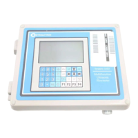
Table of Contents

Questions and Answers:

Controlotron 1010PVN Specifications

General IconGeneral
BrandControlotron
Model1010PVN
CategoryMeasuring Instruments
LanguageEnglish

Summary

1. GETTING STARTED

1.2 IMPORTANT SAFETY CONSIDERATIONS

Key safety precautions and warnings for installation and operation of the flowmeter.

1.3 FLOWMETER INSTALLATION STEPS

Outlines the typical sequence of actions required to install the flowmeter system.

1.5 THE 1010PVN KEYPAD

1.7 HOW TO USE THE INSTALLATION MENU

1.7.1 ACCESSING AND LEAVING THE MENU

Guide on accessing, navigating, and entering data within the flowmeter's installation menu.

1.7.2 HOW TO ENTER DATA

Instructions for entering data, including selecting items from lists and numeric entry.

1.7.3 THE METER TYPE MENU

2. THE 1010PVN INSTALLATION MENU

The conventions used with these instructions

Explains the conventions used for keypad keys and menu cell references.

General Installation Menu Notes

Provides important notes regarding power failures, saving site data, and custom defaults.

2.1 THE CHANNEL/PATH SETUP MENU

2.1.1 HOW TO RECALL A SITE SETUP

Procedure for reinstalling the system at a former site by recalling a saved Site Setup.

2.1.3 HOW TO CREATE/NAME A SITE SETUP

2.1.4 HOW TO ENABLE/DISABLE SITE SECURITY

2.2 THE PIPE DATA MENU

2.2.1 HOW TO SELECT A PIPE CLASS

2.2.2 HOW TO SELECT A PIPE SIZE

2.3 THE APPLICATION DATA MENU

2.3.1 HOW TO SELECT A LIQUID CLASS

Setting The LiquIdent™ Slope

Setting The Pressure Slope

Setting the LiquIdent™ Index

2.3.4 PIPE CONFIGURATION

2.4 THE PICK/INSTALL XDCR (Transducer) MENU

2.4.1 HOW TO SELECT A TRANSDUCER MODEL

2.4.8 HOW TO USE [INSTALL COMPLETED?]

2.4.10 ZERO FLOW ADJUST MENU

AutoZero

Routine invoked at the end of Initial Makeup to automatically zero offset.

2.5 THE OPERATION ADJUST MENU

Operation Adjust Menu Structure

Overview of the menu structure for adjusting operation parameters.

2.5.1 DAMPING CONTROL

2.5.2 DEADBAND CONTROL

2.6 THE FLOW/TOTAL UNITS MENU

2.6.1 FLOW VOLUME UNITS

2.6.2 FLOW TIME UNITS

2.6.6 TOTALIZER SCALE

2.6.7 TOTAL RESOLUTION

2.7 THE DATA SPAN/SET/CAL MENU

2.7.1 SPAN DATA

Sets 0% and 100% output limits for volumetric flow, absolute flow, and sonic velocity.

2.7.2 SET ALARM LEVELS

Configures system alarm functions and assigns them to relays for monitoring events.

2.7.3 CALIBRATE FLOWRATE AND CALIBRATION TABLES

Conditions calibration performance of flowrate output using intrinsic, Kc, or calibration tables.

2.8 THE STRIPCHART SETUP MENU

2.9 THE DATALOGGER SETUP MENU

2.10 THE I/O DATA CONTROL MENU

2.10.1 ANALOG OUTPUT SETUP

Assigns data functions for current, voltage, and pulse-rate analog outputs.

2.10.2 RELAY SETUP

Assigns functions to channel relays for alarm and pulse outputs.

2.10.3 ANALOG INPUT SETUP (optional function)

Assigns active analog input to a measurement channel/path, enabling port and scaling.

2.11 THE DIAGNOSTICS DATA MENU

2.11.1 MAIN DIAGNOSTICS DATA SCREEN

Displays flow, application, liquid, and site setup information for analysis.

2.11.2 FLOW DATA MENU

Displays live flow-related output data, including rate, total, and alarm status.

2.11.5 THE SITE SETUP DATA MENU

Provides data on transducer characteristics and operation for technical interpretation.

2.11.6 THE TEST FACILITIES MENU

Offers commands for system analysis, recovery, and troubleshooting using routines like Makeup and Graph.

2.11.7 TROUBLESHOOTING TIPS

Provides guidance on resolving system malfunctions and interpreting flow computer messages.

Flow Computer Messages

Lists common messages and their explanations to help diagnose problems.

2.11.8 TROUBLESHOOTING WITH TRANSDUCER TEST BLOCKS

2.12 GUIDE TO A SMOOTH INSTALLATION

CHECKLIST FOR 1010 STARTUP & PERFORMANCE

A checklist to ensure proper setup and initial operation of the 1010 system.

3. HARDWARE INSTALLATION GUIDE

3.1 PREPARING TO MOUNT THE TRANSDUCERS

Steps involved in preparing for transducer mounting, including location and pipe preparation.

3.1.3 CLAMP-ON TRANSDUCER MOUNTING MODES

Describes Direct and Reflect mounting modes for clamp-on transducers.

3.1.4 PREPARING THE PIPE

Instructions for preparing the pipe surface to ensure proper transducer contact.

3.1.5 REFLECT MODE WITH EZ CLAMP AND SPACER BAR ONLY

Details mounting transducers in Reflect Mode using EZ Clamp and spacer bar.

3.1.6 DIRECT MODE WITH EZ CLAMP AND SPACER BAR ONLY

Explains mounting transducers in Direct Mode using EZ Clamp and spacer bar.

3.1.7 REFLECT MODE - MOUNTING FRAMES AND SPACER BAR

Describes mounting in Reflect Mode using frames and a spacer bar for rigidity.

3.1.9 DIRECT MODE - MOUNTING FRAMES, SPACER BAR AND SPACING GUIDES

Recommends mounting Direct Mode transducers using frames, spacer bar, and guides for alignment.

3.1.10 USING 1012T MOUNTING TRACKS

Instructions for using 1012T mounting tracks for transducer installation.

3.2 MOUNTING TEMPERATURE SENSORS

3.2.1 WIRING TEMPERATURE SENSOR TO THE ANALOG INPUT MODULE

Steps for wiring temperature sensors to the flowmeter's analog input module.

4. THE METER FACILITIES MENU AND GRAPHIC DISPLAY SCREENS

4.1 PREFERRED UNITS

Sets the default measurement units for all meter items and data outputs.

4.2 THE TABLE SETUPS MENU

Allows pre-conditioning of pipe and transducer types for site setup defaults.

4.2.1 PIPE TABLE

Describes the factory-programmed pipe table for loading pipe data and selecting pipe classifications.

4.3 TRANSDUCER TYPE MENU

Helps generate a list of suitable transducer sizes based on pipe and liquid data.

4.4 THE DATALOGGER CONTROL MENU

4.5.1 THE ANALOG OUTPUT TRIM MENU

4.5.2 CURRENT OUTPUT TRIM (Io1 & Io2)

4.5.3 VOLTAGE OUTPUT TRIM (Vo1 & Vo2)

4.6 THE RTD CALIBRATE MENU (optional)

4.6.1 RTD CALIBRATION BY DATA ENTRY

Adjusts the intrinsic RTD reading to match an external reference thermometer.

4.7 THE CLOCK SET MENU

4.8 RS-232 SETUP

4.11 THE 1010 GRAPHIC DISPLAY SCREENS

5. SYSTEM 1010 APPLICATION NOTES

5.1 TO OBTAIN TECHNICAL ASSISTANCE

Information on how to contact Technical Service for support and troubleshooting assistance.

5.2 CONSIDERATIONS FOR CRITICAL APPLICATIONS

Factors affecting flow measurements in critical applications like custody transfer and nuclear safety.

5.3 PIPE CONSIDERATIONS FOR CLAMP-ON TRANSDUCER

5.3.2 PICKING THE APPROPRIATE TRANSDUCER

Guidance on selecting the correct transducers based on pipe diameter, temperature, and precision needs.

5.3.7 DATA STABILITY

Discusses factors influencing data stability, including data scatter and drift.

5.4 FLOW CONDITIONS

5.4.1 LOW FLOW RATES

Discusses the system's performance at low flow rates and potential issues with data scatter.

5.4.2 FLOW DATA SCATTER AND DAMPING

Explains how to manage flow fluctuations using damping and slew controls for smoother output.

5.4.3 NOTES ON LIQUID CONDITIONS

Information on how liquid properties like aeration and viscosity affect measurement performance.

TERMINOLOGY CHART

APPENDIX A

Couplant Installation Instructions

Detailed instructions for the proper installation and application of couplant materials.

APPENDIX B

SITE SETUP CONSIDERATIONS FOR 1010N BLIND SYSTEMS

Hardware and software requirements for programming blind units via PC and RS-232 interface.

APPENDIX C

ENGINEERING DRAWINGS

References to installation and dimension drawings for flow computers, transducers, and accessories.

Related product manuals