3-4
1010PVNFM-3A
Section 3
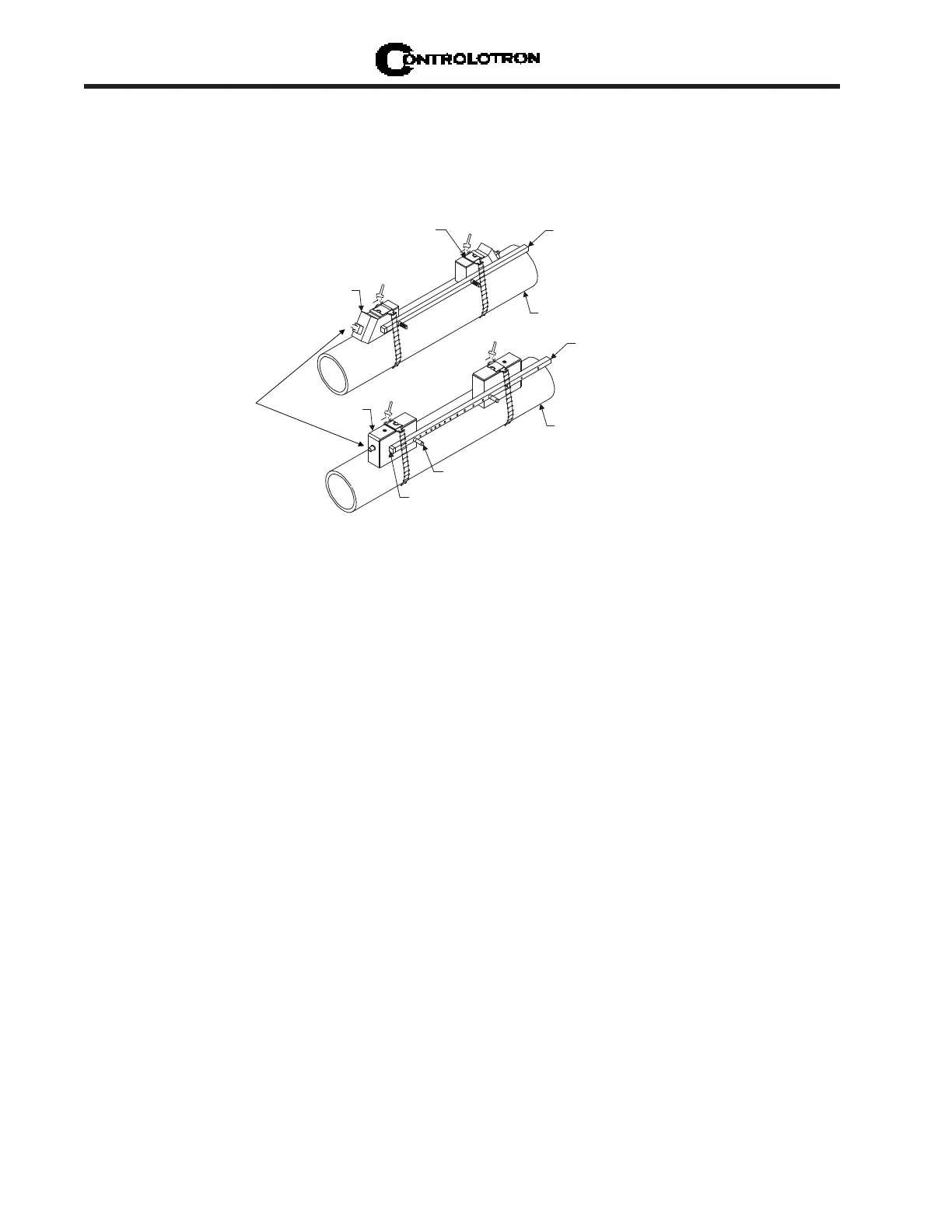
3.1.5 REFLECT MODE WITH EZ CLAMP AND SPACER BAR ONLY
The EZ Clamp is a quick and easy way to securely mount transducers on any pipe. The spacer
bar eliminates manual spacing measurements and provides rigidity for mounting the trans-
ducers while maintaining axial alignment.
Customer's Pipe
Spacer Bar
Customer's Pipe
Index Screw
Transducer
Transducer Index
Screws-Storage
1011PPS Series
Transducer
Transducer
1
0
1
1
H
P
S
S
e
r
i
e
s
Spacer Bar
Cable Connection
INSTALLATION - REFLECT MOUNT WITH EZ CLAMP AND SPACING BAR
1. Perform all required menu steps until the flow computer issues the number index and
prompts you to press [ENT] to finish the transducer install routine. Stop at this point. Note
the number index value displayed in the Pick/Install menu. You will use this number to
properly space the transducers. Check to ensure that you have a matched set of transduc-
ers. They both should have the same S/N number but marked with either an “A” or “B” (e.g.,
100A and 100B).
2. Assemble the transducers to the spacer bar, with the cable connectors facing away from
each other as shown above. The spacer bar is attached to a transducer using a transducer
index screw. One transducer is attached using the “REF” hole on the spacer bar. The sec-
ond transducer is attached to the spacer at the index hole specified in Step 1. Note that in
some cases, the transducers may have two sets of holes for securing the transducers. When
using the EZ Clamp assembly, use the lower set of holes when attaching the spacer bar.
3. Temporarily position the assembly (in the 9 o’clock position) at the location where you have
determined it would be mounted. Ensure that this is a smooth area without any raised
spots (seams, etc.). Mark a generous area around the transducers (with a pencil or chalk)
where they contact the pipe. Remove the assembly.
4. Prepare the two areas you marked by de-greasing the surface, if needed, and removing any
grit, corrosion, rust, loose paint or surface irregularities with the abrasive pipe condition-
ing material provided.
5. Remove the transducer from the spacer bar that was attached through the REF hole. Attach
the EZ clamp to the transducer under the spring clip. The adjusting nut knob should be
pointing up and on the side opposite of the spacer bar. Unscrew the knob until it’s at the
stop.