2-21
1010PVNFM-3A
Section 2
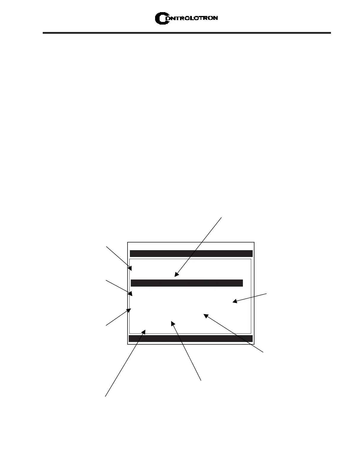
2.4 THE PICK/INSTALL XDCR (Transducer) MENU
Use this menu after creating a new site setup in the Channel Setup menu, and defining the
pipe parameters in the Pipe Data menu.
Based on pipe data (and optionally application data) entries, the Pick/Install Xdcr menu auto-
matically identifies the most suitable transducers for the application. It recommends the ap-
propriate mounting mode (direct or reflect) and lists the Spacer Bar or Mounting Track part
number and spacing index. Ideally, you will be able to use the primary recommendations.
However, you can edit the menu entries as required to accommodate different transducers or
mounting configurations.
The 1010PVN will adjust its parameters to optimize performance based on your selections.
The Ltn menu cell shows the required spacing distance (in inches or millimeters) between the
upstream and downstream transducers. Use the [Install Completed?] menu cell to inform the
flow computer that you completed the physical mounting of the transducers. You can define
the empty pipe and zero flow values once the transducers are operational.
NOTE: It would probably be most beneficial to you at this point to read Section 3
before proceeding to mount transducers.
NOTE: When installing transducers do not key in the V/M (Version/Modification) label
number as the Transducer Size.
Controlotron Dual Path SITE1
Install Path 1
Transducer Model 1011 Universal
Transducer Size B3
Xdcr Mount Mode Reflect
Spacing Offset Minimum Flow
Number Index 7
Spacing Method Track 1012TP
Ltn Value (in) 0.778
Install Completed? No
Empty Pipe Set Path Not Setup
Zero Flow Adjust Path Not Setup
Recommended Xdcr Mount Mode [Reflect]
Pick/Install Xdcr
This menu cell tells
you the model
number of the
appropriate
hardware for your
transducers and
spacing
requirements.
This menu cell
shows the actual
spacing distance
required between
the transducers.
This menu cell
identifies the spacing
index on the spacer
bar. You must use
this setting to mount
your transducers
properly.
Use this menu cell to
select the type of
transducer to be
This menu cell
allows you to select
a mounting mode.
*Use Reflect Mode
whenever possible.
After the transducers are
operating, you can use
this menu cell to
manually set the zero
flow correction.
Once you select the
type, use this menu
cell to specify the
transducer size.
Use this menu cell to
inform the meter that
you’ve completed the
transducer mounting.
After the transducers are
operating, use this menu
cell to set the empty pipe
threshold.