3-9
1010PVNFM-3A
Section 3
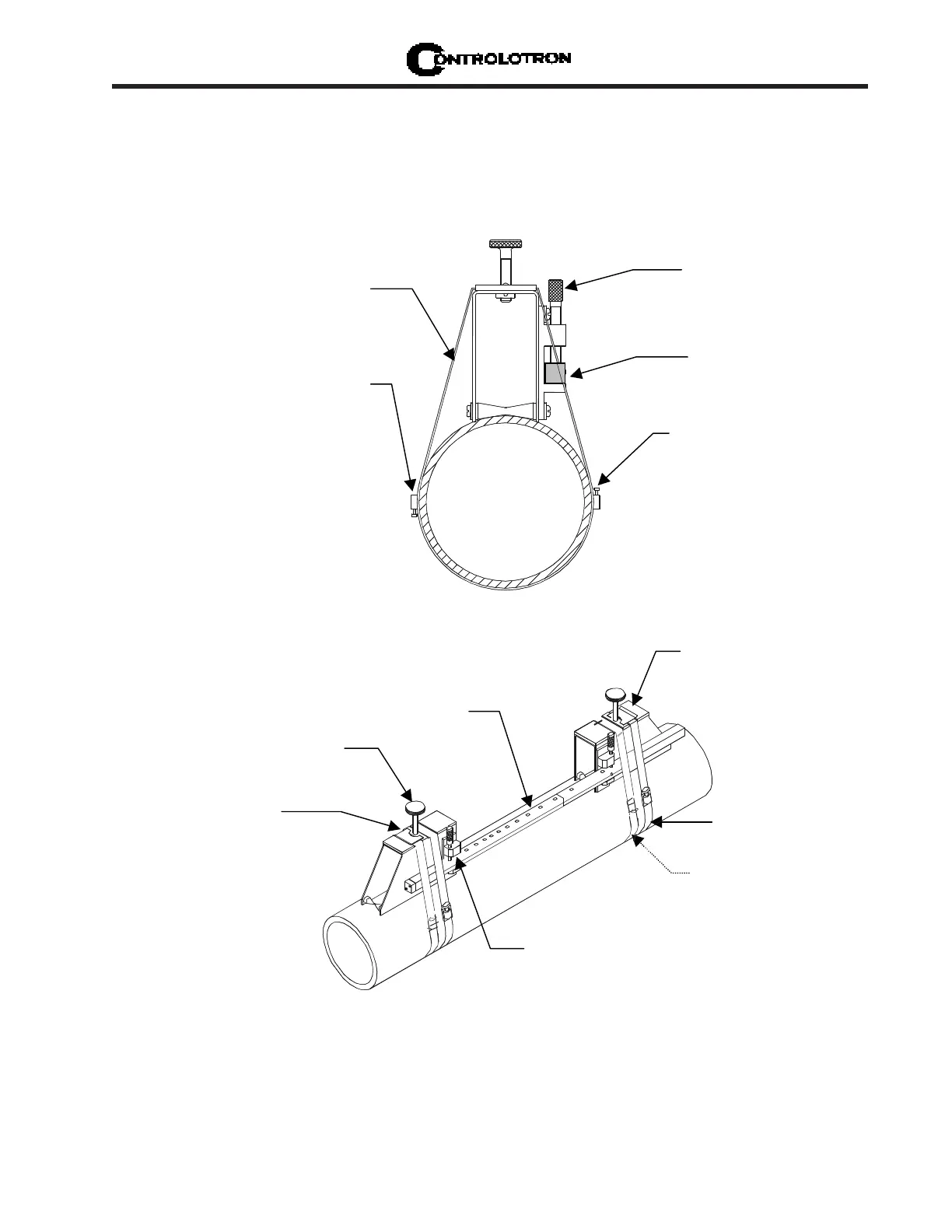
3.1.7 REFLECT MODE - MOUNTING FRAMES AND SPACER BAR
The combination of a spacer bar with mounting frames is the easiest way to mount in Reflect
Mode. The result is a rigid structure that eliminates spacing measurements, and maintains
the transducer-to-transducer geometry. In addition, reflect mounting allows you to move the
entire assembly while maintaining the original transducer spacing.
Mounting Strap
positioned around
Mounting Frame
Mounting Strap
Adjusting Screw
Optional on larger pipes,
you can link straps together
to surround pipe
Spacer Bar
(Front view)
Spacer Bar Platform &
Clamping Screw
1. Perform all required menu steps until the flow computer issues the number index and
prompts you to press <ENT> to finish the transducer install routine. Stop at this point.
Note the number index value displayed in the Pick/Install menu. You will use this number to
properly space the transducers. Check to ensure that you have a matched set of transducers.
They both should have the same S/N number but marked with either an “A” or “B” (e.g., 100A
and 100B).
Mounting Strap
Transducer Clamping
Screw
need an additional
strap for a more
secure mount
Spacer Bar
Spring Clip
(Not present on some
models)
1012 Series
Mounting Frame
Spacer Bar
Platform and
clamping screw
INSTALLATION - REFLECT MOUNT WITH FRAMES AND SPACER BAR
NOTE: Minimum Ltn 0.75 in. (18 mm)