3-21
1010PVNFM-3A
Section 3
The 991TW insert sensors are designed to be used in pipes equipped with Thermowells. These
are spring-loaded, 1/4” diameter sensors with 1/2” NPT integral connection heads, available in
several lengths to accommodate a range of pipe sizes. Thermowells for new installations are
available from Alloy Engineering Company in Bridgeport, Connecticut.
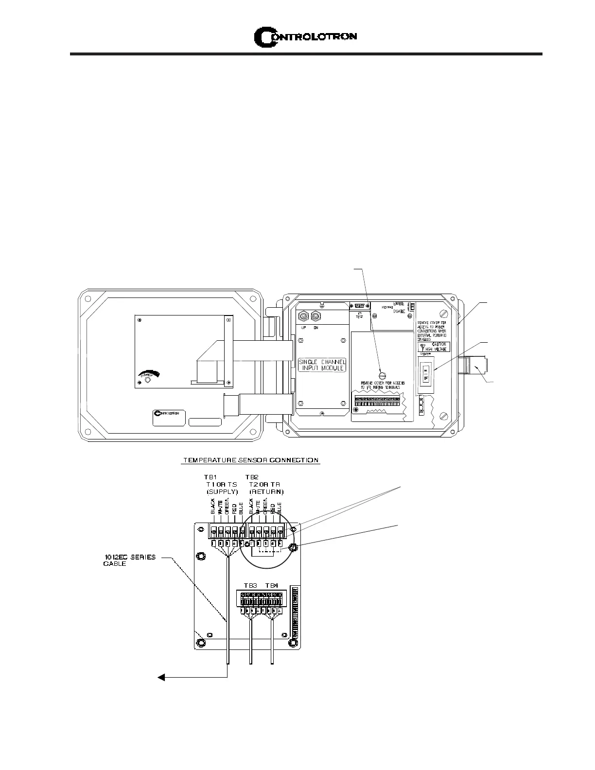
3.2.1 WIRING TEMPERATURE SENSOR TO THE ANALOG INPUT MODULE
WARNING: Set flowmeter and instrumentation power to OFF when inserting or re-
moving the Analog Input Module, or when making connections to TB1,
TB2, TB3, and TB4.
l Open the 1010PVN flowmeter top cover by releasing the cover latch.
l Place the power switch to the OFF position.
l Loosen the captive thumbscrew securing the Access Cover and remove Access Cover.
l Using a flat-blade screwdriver, remove four captive screws securing the I/O board.
l Carefully remove the I/O board and set it aside.
Access Cover
Screw
1010PVN
Power Switich
Latch
1010PVN Single Channel Temperature Sensor Inputs
TOP VIEW
SHORT TERMINALS 1 AND 4
SINCE T2 IS NOT BEING USED
- see note below.
NOTE: If this meter is using only one RTD
temperature sensor, short terminals
1 and 4 of TB2 with a jumper wire to
complete the dual RTD current loop.
Refer to paragraph 3.2.1 step 3
on next page.