2-63
1010PVNFM-3A
Section 2
2.10.2 RELAY SETUP
Use this menu to assign a function to channel relays. System 1010 supports 2 types of re-
lay outputs, Alarm Relay and Pulse Relay. Alarm Relay outputs operate in “fail-safe” mode.
The relay(s) are energized under normal conditions - an alarm condition causes the relay(s) to
de-energize until alarm clears. The Pulse Relay output supports totalizer and batch relay
functions. The output pulse width is approximately 200 ms; maximum activation rate is 2.5
pulses per sec. If totalizer pulses exceed this rate, excess pulses are stored in an overflow
register. This allows the relay to “catch up” when flow decreases enough.
NOTE: Using the key (Totalizer clear command) also clears all channel totalizers
plus the overflow register described in the last paragraph.
Assigning Relay 1 and 2 Functions
The 1010PVN, depending on the model, provides four alarm relays. Please refer to the Hard-
ware Installation Drawing for wiring details. Relays respond to any of the alarm conditions or
data functions included on the Relay Option List.
F1
1010PVCDN (Expanded 1010N-7 I/O Module)
Installation Drawing 1010N-7-7 (Sheet 3 of 3)
(Ultra Performance Flowmeters)
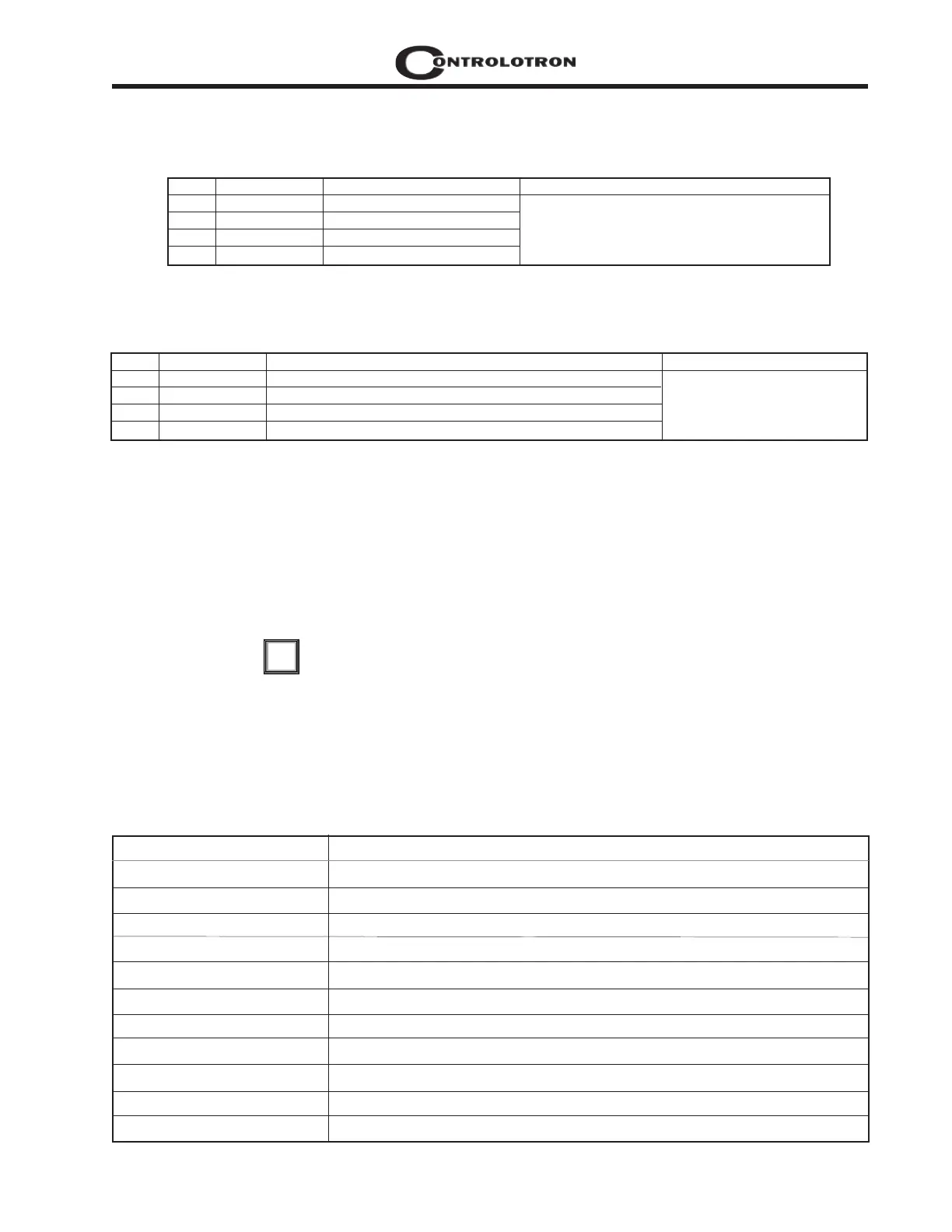
PIN# SIGNAL FUNCTION NOTES
9 PG1 PRIMARY FREQUENCY OUTPUT / OPEN COLLECTOR Digitally Synthesized
10 PG2 PRIMARY FREQUENCY OUTPUT / TTL Pulse Waveform
11 PG3 QUADRATURE FREQUENCY OUTPUT / OPEN COLLECTOR
12 PG4 QUADRATURE FREQUENCY OUTPUT / TTL
TB2
Not Used Not Active
Power Off Power Off alarm occurs when power fails
S High LiquIdent™ High LiquIdent™ value relay trip-point.
S Low LiquIdent™ Low LiquIdent™ value relay trip-point.
S High Temperature High temperature value relay trip-point.
S Low Temperature Low temperature value relay trip-point.
S High Flow System flow rate exceeds high flow setpoint.
S Low Flow System flow rate falls below low flow setpoint.
S Flow Alarm System flow rate exceeds or falls below flow setpoints.
S Fault Alarm System loses receive signal (all paths in fault).
S Soft Fault Fault condition - memory mode active.
S Spacing System transducer spacing needs adjusting.
Relay Option List
PIN# SIGNAL FUNCTION NOTES
9 PG1 FREQUENCY OUTPUT 1 0 - 5000 Hz, 5 Volt Logic, Square Waveform
10 PG2 REF. GROUND
11 PG3 FREQUENCY OUTPUT 2
12 PG4 REF. GROUND
1010PVN & 1010PVDN with Expanded 1010N-7 I/O Modules
Installation Drawing 1010N-7-7 (Sheet 2 of 3)
(Standard, High Performance and Enhanced Performance Flowmeters)
TB2