2
SETTING UP
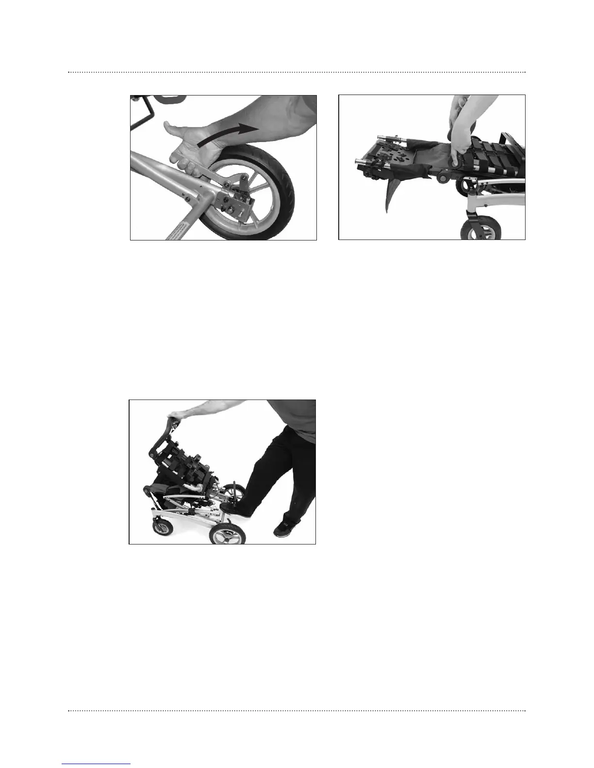
Fig. 5
Fig. 6
4. Apply wheel locks. Fig. 4
5. Push in gray detent buttons on handle, and lift upward until handle is
at a 90-degree angle with chair. Fig. 5
6. Grasp handle, place foot on the frame’s lower support tube, and pull
upward on chair until the red safety lock clicks into place. Fig. 6
7. Adjust handle and footplate i nto desi red posi ti on.
Fig. 4