Layout and function
Installation manual 13
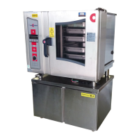
► Layout and function of the combi steamer (standard controls)
Table-top appliance construction
The following diagram shows a gas appliance and an electric appliance, representing all table-top
appliances:
6019050_01
R
1
32
4
5
6
7
5
8
12
10
11
9
OGB 10.10 OEB 10.10
6019050_01
R
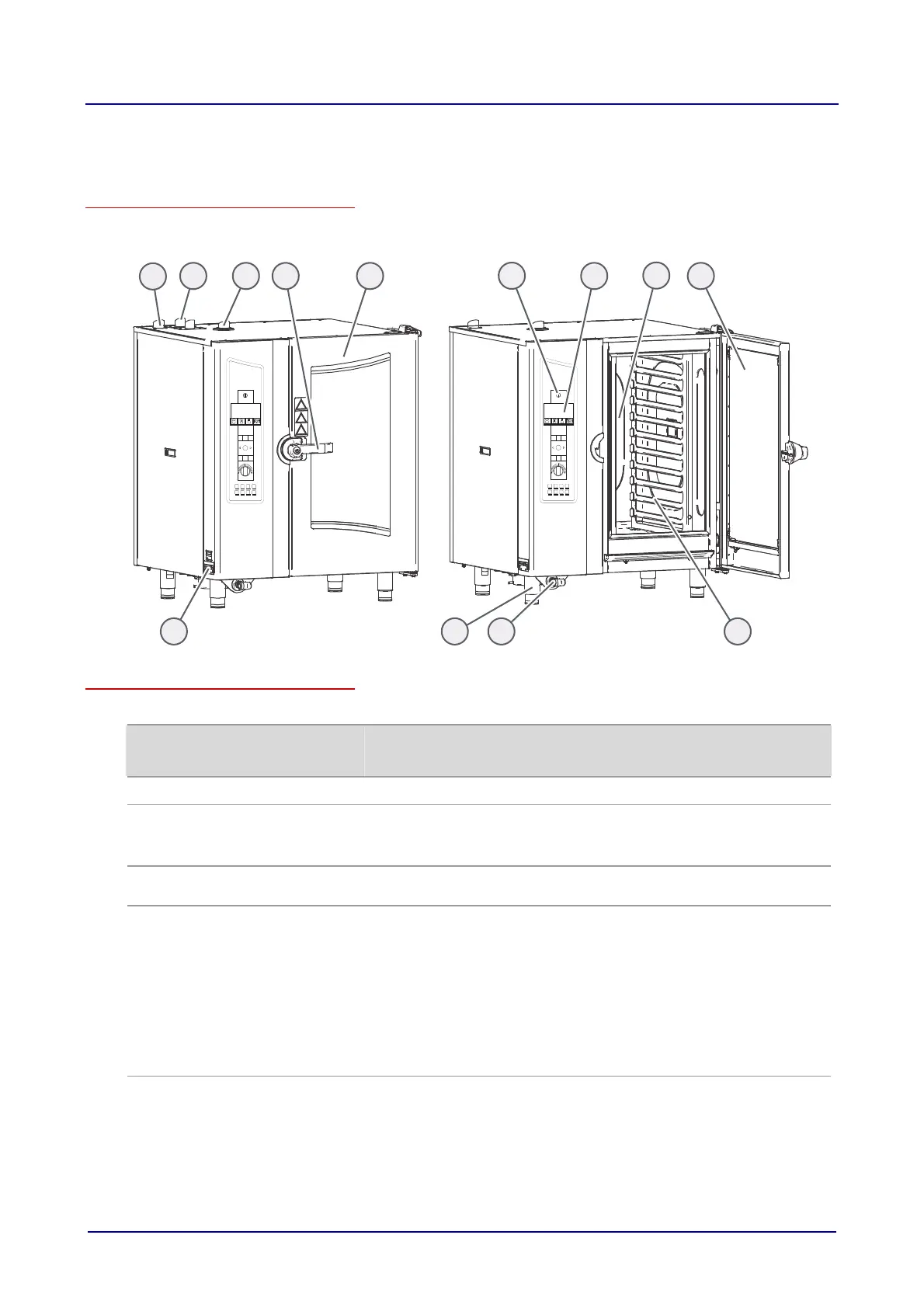
Components of the table-top appliances and their function
The components of the table-top appliances have the following function
No. Name
Picture
Function
1
Air vent Controls ventilation
2
Gas flue pipe
On gas appliances only (vents flue gases):
1 gas flue pipe on appliances with injection
2 gas flue pipes on appliances with steam generator
3
Low-pressure failsafe device
Prevents the low pressure in the oven e.g. during fully automatic cleaning
(CONVOClean system)
4 Multi-function door handle
("Hygienic Handle")
Has the following functions depending on its position:
Pointing vertically downwards: combi steamer closed, ready for cooking
Horizontal: combi steamer open, in on-latch position
20 degrees above horizontal: Combi steamer can be opened
Also has the following functions:
Additional function as far as on-latch position
In the on-latch position, door can be opened from inside oven in an
emergency
Antibacterial with silver ions
5 Appliance door ("disappea-
ring door")
Seals the oven during cooking
Special opening action allows it to slide back against the side of the
combi steamer to save space
 Loading...