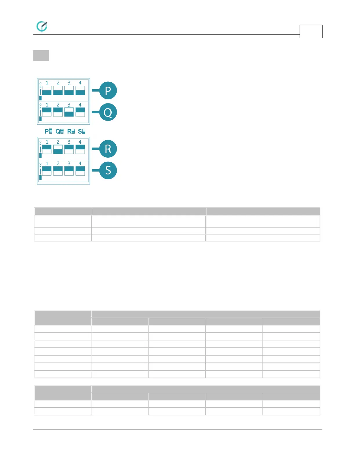
DIP Switches
CoolMasterNet PRM Rev 0.7
14
www.coolautomation.com
© 2017 CoolAutomation
5
DIP Switches
DIP Switches are located behind the small access door at the upper right side of the CoolMasterNet.
DIP Switch P
Link L6,L7 and enable polarity auto-detection on
L7
Notes:
· Switches P1 and P2 should be in the same position. If they are both in ON position, HVAC Lines L6 and L7
are linked into one line with option to auto-detect line polarity. Otherwise, if both P1 and P2 are in OFF
position HVAC Lines L6 and L7 are separate independent lines.
· If L6 and L7 are linked into L7, enabling of the L2 with P3 will not influence on L7 operation.
· Switch P4 must be in OFF position for normal operation of CoolMasterNet.
DIP Switches Q,R
DIP Switched Q and R are used to adjust HVAC Lines L1 and L2 internal parameters to meet specific HVAC
type requirements.
DIP Switch Q - HVAC Line L1
DIP Switch R - HVAC Line L2