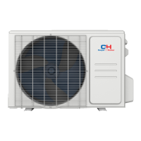
COOLING
HEATING
4-Way valve
Discharge
Suction
Heat
exchanger
(evaporator)
Heat
exchanger
(condenser)
Valve
Valve
Liquid pipe
side
Gas pipe
side
Strainer
Electron
expansion
valve
Strainer
Capillary
Accumlator
Compressor
Refrigerant pipe diameter
Liquid :1/4" (6 mm) Gas : 3/8" (9.52mm)(9、12K); 1/2"(12mm)(18K); 5/8"(16mm)(24K)
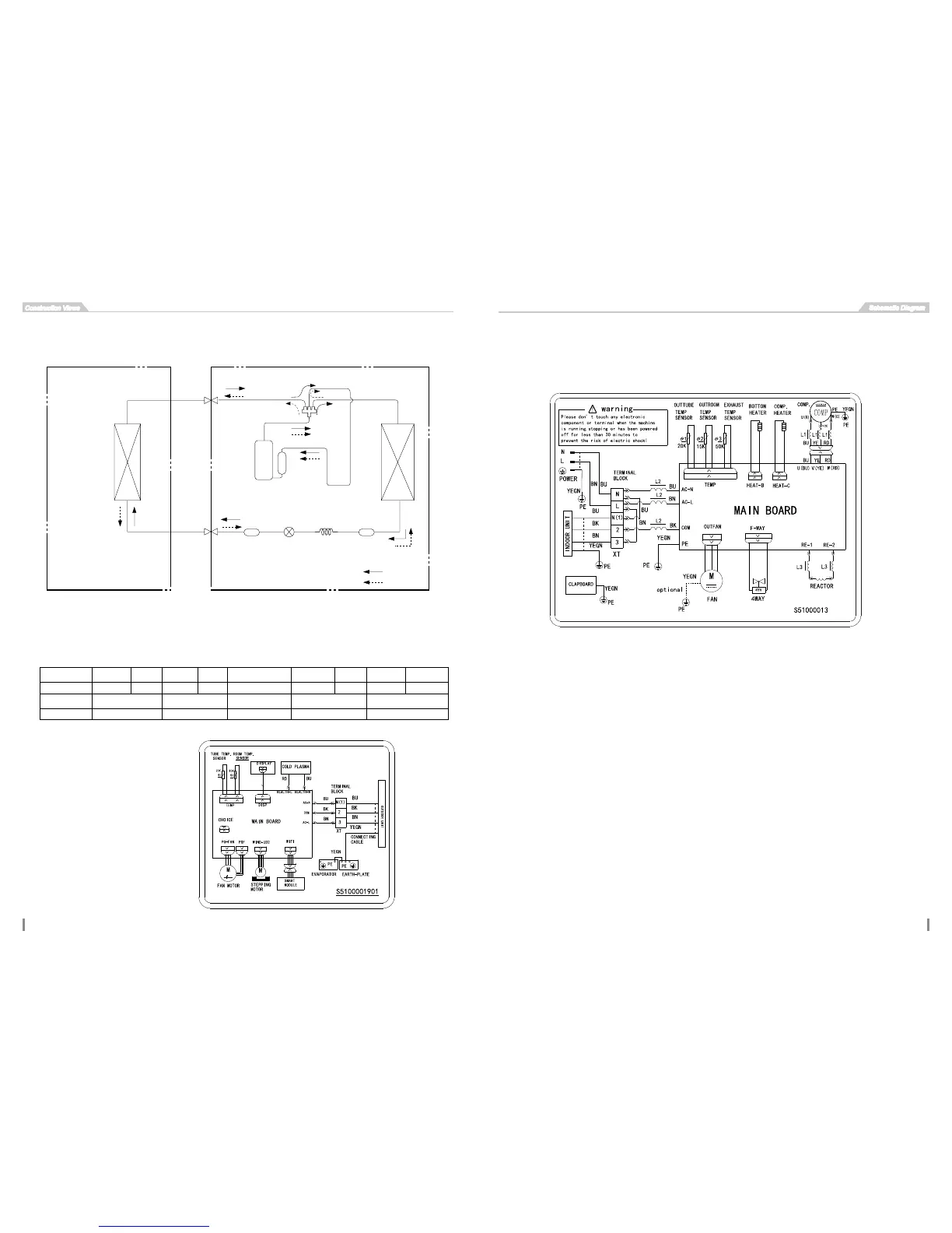
5. Schematic Diagram
5.1 Electrical Wiring
Symbol OG WH YE RD YEGN BN BU BK VT
Color symbol ORANGE WHITE YELLOW RED YELLOW GREEN BROWN BLUE BLACK VIOLET
Symbol COMP CT1,2 4V XT
Parts name COMPRESSOR OVERLOAD 4-WAY VALVE TERMINAL BLOCK PROTECTIVE EARTH
Meaning of marks
Indoor unit
Outdoor unit
These circuit diagrams are subject to change without notice, please refer to the one supplied with the unit.