When installing the recloser, refer to the applicable recloser-
mounting frame instructions. Installation instructions are
included with the mounting frame.
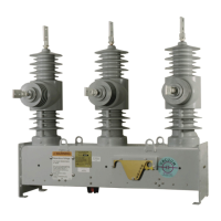
1. Check the data plate ratings. Make sure the rat-
ings, settings, and interface options on the recloser
data plate (Table 7 and Figure 14) are correct for the
planned installation.
2. Perform high-potential withstand tests. Prior to
installing the NOVA recloser, perform high-potential
withstand tests. Refer to the Service Information sec-
tion for high-potential withstand test procedures.
3. Install the recloser. Install the recloser in the appro-
priate Cooper Power Systems pole- or substation-
mounting frame. Refer to Figure 7 for moving and lifting
instructions.
• Before hanging the recloser on the pole, manually
open the unit by lowering the yellow handle.
Type NOVA Three-Phase, Microprocessor-Controlled Recloser Installation and Operation Instructions
8
WARNING: This equipment is not intended to
protect human life. Follow all locally approved
procedures and safety practices when installing or
operating this equipment. Failure to comply can result in
death, severe personal injury, and equipment damage.
G102.1
WARNING: Hazardous voltage. Always use a
hotstick when working with this equipment. Failure
to do so could result in contact with high voltage,
which will cause death or severe personal injury.
G108.1
CAUTION: Follow all locally approved safety practices
when lifting and mounting the equipment. Use the lifting
lugs provided. Lift the unit smoothly and do not allow
the unit to shift. Improper lifting can result in equipment
damage. G106.2
CAUTION: Personal injury. Sheds on epoxy
encapsulation have sharp edges. Wear protective
gloves when handling the unit. Failure to do so can result
in cuts and abrasions. T258.1
INSTALLATION PROCEDURE
†
Serial number format: CP57#####XY
*Auxiliary-powered with 14-pin control receptacle
**Control-powered with 19-pin control receptacle
TABLE 7
Nameplate Stamping
†
Stamping
Option X Y
Act 1 Interface with VSAM A
Act 2 Interface with VSAM (small actuator) B
Act 2C Interface with VSAM (large actuator) C
Act 2C Interface with VBSI D
Act 2C Interface with VSAM (small actuator) E
Act 2C Interface with VBSIb J
48 VDC Interface Input / 48 VDC Heater A*
48 VDC Interface Input / 120 VAC Heater B**
48 VDC Interface Input / 240 VAC Heater C**
125 VDC Interface Input / 125 VDC Heater D*
250 VDC Interface Input / 250 VDC Heater E*
120 VAC Interface Input / 120 VAC Heater H*
240 VAC Interface Input / 240 VAC Heater J*
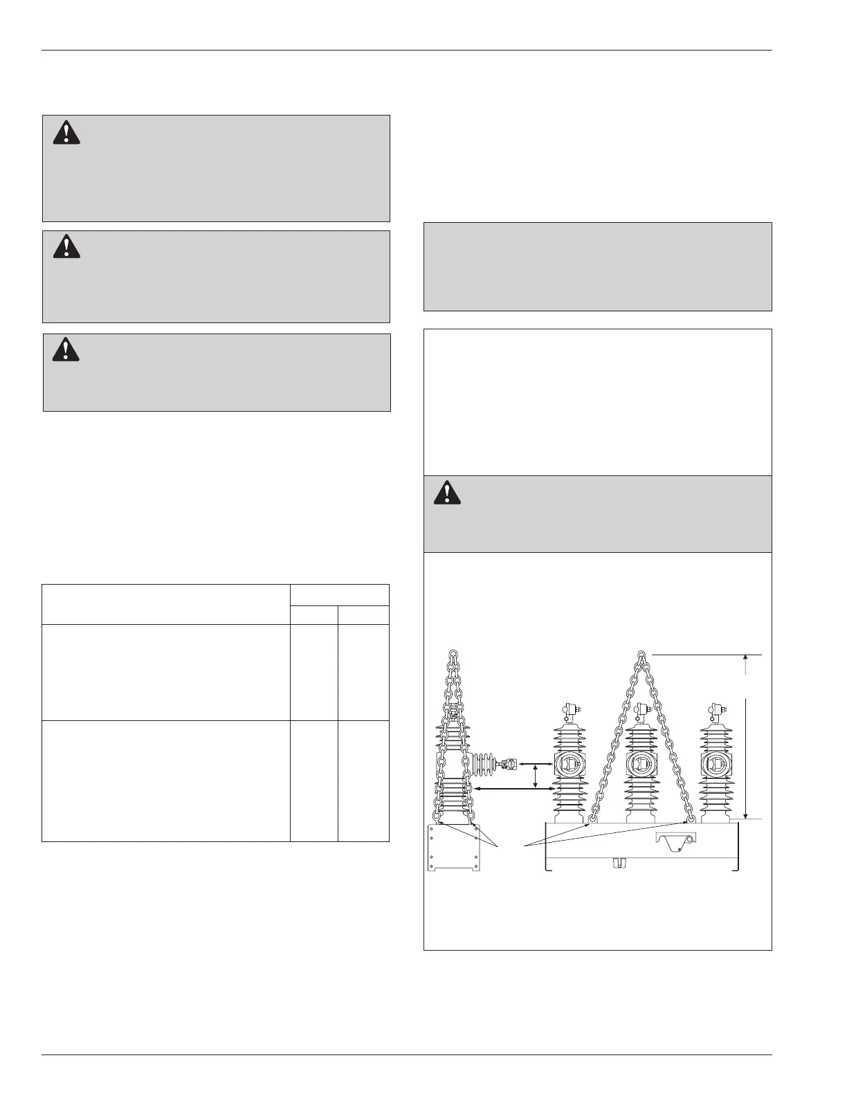
Figure 7.
Moving and lifting the Type NOVA recloser.
Moving the Recloser
Type NOVA reclosers are shipped palletized (bolted onto
a pallet). When moving with a fork truck/lift, the recloser
must remain bolted to the pallet to avoid damage to the
OPEN/CLOSE contact position indicator.
Cooper Power Systems recommends transporting
NOVA reclosers in the closed position to maximize the
operational performance of the unit.
Lifting the Recloser
Follow all approved safety practices when making hitch-
es and lifting the equipment. Lift the unit smoothly and
do not allow the unit to shift.
A: Sling height for 15 kV and 27 kV with 125 BIL units: 914 mm (36 in)
Sling height for 27 kV with 150 BIL and 38 kV units: 1067 mm (42 in)
B: Center of gravity (Cg) is approximately 100 mm (4 in) below plane of
lower terminals.
CAUTION: Tip-over Hazard. High center of grav-
ity. Use a 4-point hitch to prevent switchgear from
overturning during lifting operations. Improper lifting can
result in personal injury or equipment damage. T297.0