EasyManua.ls Logo

Cooper Power Systems NOVA 15 - User Manual

Cooper Power Systems NOVA 15
28 pages
Print Icon
To Next Page IconTo Next Page
Loading...
Types NOVA 15, NOVA 27, and NOVA 38;
Three-Phase Microprocessor-Controlled;
Installation and Operation Instructions
Reclosers
Service Information
Safety Information ..................................................... 2
Hazard Statement Definitions ................................. 2
Safety Instructions .................................................. 2
Product Information .................................................. 3
Introduction ............................................................ 3
Acceptance and Initial Inspection ........................... 3
Handling and Storage .............................................. 3
Standards .............................................................. 3
Description of Operation ......................................... 3
Ratings and Specifications ....................................... 4
Check Recloser Ratings Prior to Installation ........... 4
Dimensions ................................................................ 5
NOVA Mechanism Interface Options ....................... 6
Control-Powered Interface ..................................... 6
Auxiliary-Powered Interface ..................................... 7
Installation Procedure ............................................... 8
Moving the Recloser ............................................... 8
Lifting the Recloser ................................................. 8
Remove Recloser from Service .............................. 11
Grounding the NOVA Recloser ............................... 11
Operation ................................................................... 14
Electrical Operation ................................................ 14
OPEN/CLOSE Contact Position Indicator ............... 14
Hotstick Operation (Manual Open, Electrical Close) ..... 14
Internal Voltage Sensing Option .............................. 15
Accessories ............................................................... 19
Auxiliary Switch ....................................................... 19
Terminals ................................................................ 19
Pole-Mounting Hanger ........................................... 20
Arrester-Mounting Brackets ................................... 21
Substation-Mounting Frame ................................... 22
Service Information ................................................... 23
Service Requirements ............................................ 23
Frequency of Inspection ......................................... 23
Testing Operation ................................................... 23
High-Potential Withstand Testing ........................... 24
Module Flashover Service ....................................... 25
Troubleshooting ........................................................ 25
Unit Will Not Close ................................................. 25
Unit Will Not Open Electrically ................................ 25
Contents
S280-42-1
1
March 2011 • Supersedes 2/2011
NOVA 15 for Serial Number 3421 and above
NOVA 27 for Serial Number 3268 and above
NOVA 38 for Serial Number CP571192790 and above
This bulletin is also applicable to product
serial numbers beginning with the prefix CP57.
Figure 1.
NOVA three-phase, microprocessor-controlled recloser, shown with two-hole, flat-pad accessory.
Question and Answer IconNeed help?

Do you have a question about the Cooper Power Systems NOVA 15 and is the answer not in the manual?

Summary

Safety Information

Hazard Statement Definitions

Defines hazard statement types used within the manual.

Safety Instructions

Provides general cautionary and warning statements for safe operation.

Product Information

Introduction

Introduces the service information manual for the NOVA recloser.

Acceptance and Initial Inspection

Details procedures for inspecting the recloser upon receipt from the factory.

Handling and Storage

Provides guidance on safe handling and storage of the recloser to prevent damage.

Standards

Lists industry standards the NOVA reclosers are designed and tested to.

Ratings and Specifications

Check Recloser Ratings Prior to Installation

Emphasizes verifying recloser ratings against system characteristics before installation.

Dimensions

NOVA Mechanism Interface Options

Control-Powered Interface

Describes the control-powered interface for NOVA reclosers and its requirements.

Auxiliary-Powered Interface

Details the auxiliary-powered interface for NOVA reclosers and its compatibility.

Installation Procedure

Moving the Recloser

Provides instructions and precautions for moving the recloser safely.

Lifting the Recloser

Gives guidance on proper lifting techniques and safety for the recloser.

Remove Recloser from Service

Outlines the steps and precautions for safely removing the recloser from service.

Grounding the NOVA Recloser

Provides important grounding considerations for pole-mounted applications.

Grounding with a Local Supply Voltage Transformer

Details grounding requirements for local supply transformers.

Grounding with a Remote Supply Voltage Transformer

Details grounding requirements for remote supply transformers.

Grounding on a 3-Wire Uni-Grounded System

Explains grounding procedures for 3-wire uni-grounded systems.

Operation

Electrical Operation

Describes the electrical interface and operation of the NOVA recloser.

OPEN;CLOSE Contact Position Indicator

Explains the function and appearance of the contact position indicator.

Hotstick Operation (Manual Open, Electrical Close)

Details how to manually operate the recloser using a hotstick.

Internal Voltage Sensing Option

Form 5 Control Settings

Details programming requirements for the Form 5 control with voltage sensing.

Form 4 D and Form 6 Control Settings

Outlines programming for Form 4D and Form 6 controls with voltage sensing.

Accessories

Auxiliary Switch

Describes the three-stage auxiliary switch accessory and its ratings.

Terminals

Discusses available terminal options and recommendations for connection.

Pole-Mounting Hanger

Describes the pole-mounting hanger accessory and its dimensions.

Arrester-Mounting Brackets

Details the arrester-mounting bracket accessory and its dimensions.

Substation-Mounting Frame

Describes the substation-mounting frame accessory and its dimensions.

Service Information

Service Requirements

Outlines general service requirements and inspection intervals for the recloser.

Frequency of Inspection

Provides guidance on determining appropriate service inspection intervals.

Testing Operation

Refers to control manuals for testing procedures and basic checks.

High-Potential Withstand Testing

Test 1

Details the procedure and connections for phase-to-ground high-potential testing.

Test 2

Details the procedure and connections for phase-to-phase high-potential testing.

Test 3

Details the procedure and connections for open-contact high-potential testing.

Module Flashover Service

Troubleshooting

Unit Will Not Close

Lists common causes and checks for when the recloser fails to close.

Unit Will Not Open Electrically

Lists common causes and checks for when the recloser fails to open electrically.

Overview

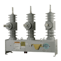
The NOVA recloser is a three-phase, microprocessor-controlled, vacuum-interrupting device designed for electrical distribution systems up to 34.5 kV. It is available in NOVA 15, NOVA 27, and NOVA 38 types, with specific serial number ranges for each. The recloser is compatible with Cooper Power Systems microprocessor-based controls, including Form 4C, Form 4D, Form 5, and Form 6.

Function Description

The NOVA recloser utilizes an interface circuit within its mechanism housing to control the opening and closing signals to a magnetic actuator. It is designed to interrupt fault currents and reclose to restore power, enhancing system reliability. The recloser's solid polymer insulation system is highly resistant to environmental factors such as ozone, oxygen, moisture, contamination, and ultraviolet light, eliminating the need for gaseous, liquid, or foam dielectrics. It operates effectively within a temperature range of -40°C to +55°C.

Important Technical Specifications

Voltage Ratings:

  • Maximum Voltage: 15.5 kV (for 15 kV models), 29.2 kV (for 27 kV models), 38.0 kV (for 38 kV models).
  • Rated Basic Impulse Level (BIL): 110.0 kV or 125.0 kV (15 kV models), 125.0 kV or 150.0 kV (27 kV models), 170.0 kV (38 kV models, for serial numbers CP571192790 and above; earlier models rated 150 kV BIL or less).
  • Power Frequency Withstand (Dry/Wet): 50 kV/45 kV (15 kV models), 70 kV/60 kV (27 kV models), 60 kV/50 kV (38 kV models).

Current Ratings:

  • Rated Continuous Current: 630 A (800 A accessory also available).
  • Short Circuit Current, Symmetrical: 12.5 kA (16.0 kA option also available).
  • Making Current, Asymmetrical Peak: 32.0 kA.
  • Cable Charging Current: 10 A (15 kV models), 25 A (27 kV models), 40 A (38 kV models).

Mechanical Ratings:

  • Min. Mechanical/Electrical Operations Without Maintenance (C-O): 10,000 operations.
  • Mass (Weight): 86 kg (190 lbs) for 15 kV models, 91 kg (200 lbs) for 15 kV and 27 kV models, 101 kg (223 lbs) for 27 kV and 38 kV models.

Duty Cycle: The recloser's duty cycle varies with the percentage of interrupting rating:

  • 15-20% interrupting rating: 88 unit operations.
  • 45-55% interrupting rating: 112 unit operations.
  • 100% interrupting rating: 32 unit operations.
  • Total: 232 unit operations.
  • Minimum Circuit X/R Value: 4 (15-55% interrupting rating), 17 (100% interrupting rating at 60 Hz).

Auxiliary-Powered Interface Power Requirements (Table 5):

  • 120 VAC: 0.2 A (Normal), 1.0 A (Operating), 3 sec (Duration), 150 VA (Recommended Power).
  • 240 VAC: 0.1 A (Normal), 0.5 A (Operating), 3 sec (Duration), 150 VA (Recommended Power).
  • 125 VDC: 0.2 A (Normal), 1.0 A (Operating), 3 sec (Duration), 150 VA (Recommended Power).
  • 250 VDC: 0.1 A (Normal), 0.5 A (Operating), 3 sec (Duration), 150 VA (Recommended Power).

Auxiliary Switch Interrupting Ratings (Table 10):

  • 24 VDC: 15.0 A (Inductive), 20.0 A (Non-Inductive).
  • 48 VDC: 7.5 A (Inductive), 10.0 A (Non-Inductive).
  • 120 VAC: 60 A (Inductive), 80 A (Non-Inductive).
  • 125 VDC: 1.5 A (Inductive), 2.0 A (Non-Inductive).
  • 240 VAC: 30 A (Inductive), 60 A (Non-Inductive).
  • 250 VDC: 0.45 A (Inductive), 0.5 A (Non-Inductive).

High-Potential Withstand Test Voltages (75% of Rated Low-Frequency Withstand Voltage, 1 minute dry, kV rms) (Table 11):

  • NOVA-15: 37.5 AC, 53.0 DC.
  • NOVA-27: 45.0 AC, 63.6 DC.
  • NOVA-38: 52.5 AC, 74.2 DC.

Usage Features

Control-Powered Interface:

  • Fully operational with Cooper Power Systems Form 4C, Form 5, and Form 6 microprocessor-based controls.
  • Requires a DC-to-DC converter, interface circuit, and a fully shielded 19-pin cable.
  • Includes a 19-pin receptacle and internal heaters for humidity control, powered by the control input power supply.
  • NOVA reclosers with serial numbers 100,000 and above (or beginning with CP57) require a Voltage Trip/Close (VTC) interface and a VTC-ready control for tripping and closing.
  • The DC-to-DC converter board charges trip/close capacitors from the control's 24 VDC battery supply to 53 VDC, enabling multiple trip/close operations even without AC power.

Auxiliary-Powered Interface:

  • Fully operational with standard Cooper Power Systems FXB, Form 4C, Form 4D, Form 5, and Form 6 microprocessor-based controls.
  • Includes both a 2-pin and a 14-pin receptacle on the recloser, along with internal heaters.
  • Compatible with 120 VAC, 240 VAC, 125 VDC, or 250 VDC auxiliary input power.
  • Trip-and-close capacitors are charged via auxiliary input power and the recloser control. The charge is maintained by the control battery upon loss of AC power, allowing for tripping and backup closing.

Hotstick Operation (Manual Open, Electrical Close):

  • The recloser can be manually opened by pulling down the yellow manual OPEN handle with a hotstick.
  • To close the recloser after a manual opening, the yellow handle must first be pushed up, then the recloser can be closed using the microprocessor control.
  • The recloser cannot be closed electrically if the yellow manual OPEN handle is in the down position.

OPEN/CLOSE Contact Position Indicator:

  • A visual indicator on the bottom of the mechanism housing shows red for CLOSED and green for OPEN.
  • It is crucial not to rely solely on the operating handle or contact position indicator to confirm de-energization; a visible disconnect must always be established.

Internal Voltage Sensing Option:

  • Uses resistive voltage dividers to provide low-voltage input to the NOVA recloser control.
  • Requires specific installation and programming procedures for Form 4D, Form 5, and Form 6 controls.
  • Horizontal bushings (1, 3, 5) must be connected to the source for proper voltage monitoring.

Terminal Options:

  • Standard eyebolt terminals (1/0-500 mcm, 630 A maximum) are recommended for copper conductors.
  • Optional terminals include eyebolt (4/0-1000 mcm, 800 A maximum), 2-hole and 4-hole flat-pad terminals, and stud-type terminals (1.125 - 12 threads, 800 A maximum).
  • Copper alloy terminals are used, and connection to copper wires is recommended to optimize electrical connection. Anti-oxide coatings should be maintained for aluminum cable connections.

Mounting Accessories:

  • Pole-Mounting Hanger: Bolts directly to the recloser frame for pole installation.
  • Arrester-Mounting Brackets: Allow for the addition of inboard and outboard arresters (arresters not included).
  • Substation-Mounting Frame: Available for substation applications, with adjustable height.

Maintenance Features

Frequency of Inspection:

  • The NOVA recloser is designed for a minimum mechanical life of 10,000 operations.
  • It should be inspected every ten years to check for physical damage and verify proper operation.
  • Service intervals may be adjusted based on actual operating experience and climatic conditions.

Testing Operation:

  • Electrical Open and Close Operation: Test by using the microprocessor control and confirming contact status via the OPEN/CLOSE indicator or continuity check.
  • Manual Open Test: Pull the yellow manual OPEN handle down and confirm contact status.
  • Closing Procedure: Push the yellow manual OPEN handle up, then close electrically via the control.
  • A 60-second wait is recommended after every fourth close/open operation, especially with fault current applied.

High-Potential Withstand Testing:

  • Performed prior to installation to confirm dielectric strength and vacuum interrupter integrity.
  • Tests include Phase to Ground, Phase to Phase, and Open Contact tests using specified AC and DC voltages for 60 seconds.
  • Requires a high-voltage test set with sensitive circuit breakers.
  • Test results for reclosers with internal voltage sensing may be influenced by the source-to-ground connected sensing resistor.

Module Flashover Service:

  • If a recloser module has been exposed to an external flashover (e.g., carbon tracking or discoloration), an inspection process is recommended.
  • Procedure includes bypassing and removing the recloser, performing a high-potential withstand test, inspecting housing, lifting lugs, terminals, operating rod, and module conductor rods for damage.
  • Damaged components must be replaced or repaired.
  • If no damage is found, the module should be cleaned with isopropyl alcohol and a scratch-free nylon scouring pad.
  • Electrical operation and dielectric strength must be confirmed before returning to service.

Troubleshooting:

  • Unit Will Not Close: Check manual open handle position, cable connections, control power, control battery level (for auxiliary-powered), auxiliary power presence (for auxiliary-powered), and fusing on the DC-to-DC converter board (for control-powered).
  • Unit Will Not Open Electrically: Check cable connections, control power, auxiliary power presence (for auxiliary-powered), and fusing on the DC-to-DC converter board (for control-powered).

Grounding:

  • Crucial for proper equipment protection, especially in pole-mounted applications.
  • Ground connections must be made between the recloser, transformer, recloser control, and SCADA equipment.
  • Specific grounding methods are provided for local and remote supply voltage transformers in 4-wire multi-grounded, 3-wire ungrounded, or impedance-grounded systems, and for 3-wire uni-grounded systems.
  • All external inputs to the control must be routed within 8 inches of their corresponding ground to minimize stress during power surges.
  • Any external voltage sensor must have its ground referenced to the recloser ground.

Cooper Power Systems NOVA 15 Specifications

General IconGeneral
BrandCooper Power Systems
ModelNOVA 15
CategoryIndustrial Equipment
LanguageEnglish