S280-42-1
15
!
SAFETY
NOW
!
SAFETY
FIRST
!
SAFETY
FOR YOUR SAKE
!
SAFETY
MAKES SENSE
!
SAFETY
USE IT
!
SAFETY
FOR LIFE
Installation
The internal voltage sensors use a resistive voltage divider
to provide a low-voltage input to the NOVA recloser control.
Refer to the Installation section of this manual for informa-
tion on the NOVA recloser installation procedure.
Refer to • S280-104-1 for further information on installing
the Form 4D control.
Refer to • S280-79-10for further information on installing
the Form 5 control.
Refer to • S280-70-3 for further information on installing
the Form 6 Pole-Mount control.
Make voltage-sensing-option connections when installing the
control as indicated in these Service Information manuals.
Verify correct grounding of the NOVA recloser and control
prior to making any high-voltage connections and before
high-potential testing. A proper ground connection con-
sists of a good electrical ground connection to the surge
ground connector located on the mechanism housing.
Provide a good electrical ground connection to the control
cabinet ground.
Note: Painted surfaces of the mechanism housing may prevent
a ground connection to the recloser housing. Always
provide a good electrical connection to the mechanism
surge ground connector.
Poor grounding of the mechanism housing may result in
the presence of high voltage on the mechanism housing
associated with the high-voltage resistor connections
used with internal voltage sensing.
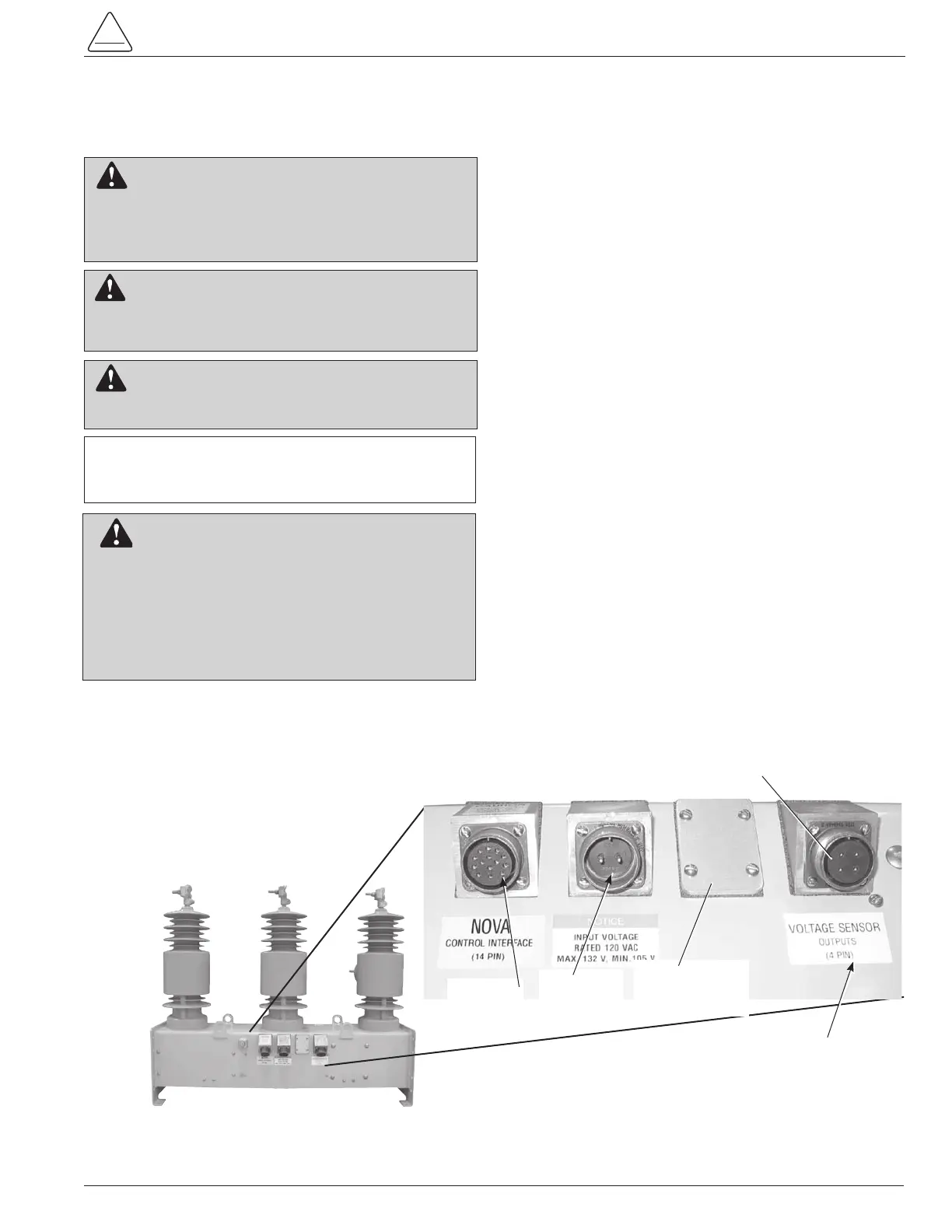
Figure 15.
Type NOVA recloser cable receptacles with internal voltage sensing option. (Type NOVA recloser with 14-pin
control interface shown.
Voltage Sensor Label
Optional
Auxiliary Switch
Receptacle
Internal Voltage Sensor Receptacle
Control
Interface
Power
Supply
Receptacle
INTERNAL VOLTAGE SENSING OPTION
IMPORTANT: Disconnect switches for AC control
power are necessary to isolate the control for testing
and servicing.
WARNING: Hazardous voltage. Always use a hot-
stick when working with this equipment. Failure to
do so could result in contact with high voltage, which will
cause death or severe personal injury. G108.1
WARNING: This equipment is not intended to
protect human life. Follow all locally approved proce-
dures and safety practices when installing or operating this
equipment. Failure to comply can result in death, severe
personal injury, and equipment damage. G102.1
WARNING: Hazardous voltage. Solidly ground all
equipment. Failure to comply can result in death,
severe personal injury, and equipment damage. T223.2
WARNING: Hazardous voltage. If terminal con-
nections are reversed, the internal voltage sensing
option may indicate zero voltage with the contacts open.
Do not rely on internal voltage sensing to ensure that
the voltage is zero and the line has been de-energized.
Always follow proper safety practices and use a separate
detection method to verify a de-energized condition.
Failure to do so can result in contact with high voltage,
which will cause death or severe personal injury. T365.0


 To Next Page