The recloser is equipped with a 4-pin female receptacle
(Figure 15) that connects to the control with a shielded,
4-conductor cable. The control accessory includes a 4-pin
male receptacle on the control and appropriate circuitry;
refer to Figures 16, 17, and 18.
The electrical connectors of the recloser, control, and
cable must be clean and dry. Contaminated surfaces may
be cleaned with denatured alcohol and wet connector
surfaces may be dried with a heat gun. Dry surfaces are
particularly important for the internal voltage sensor cable
connections. The accuracy of the sensors can be influ-
enced by moisture contamination.
Connect control cables, power cables, and sensor cables
to the control. Verify that the proper cable/receptacle con-
nections are made. Improper cable connections can result
in damage to the recloser and/or control.
Complete the control programming before making the
high-voltage line connections. Refer to the Operation
section of this manual. Verify the correct voltage rating of
the equipment. Verify the correct control programming for
ratio and phase angle correction for the voltage rating of
the equipment.
Make appropriate electrical connections to the terminals of
the recloser. Verify the correct load-side (vertical bushings)
and source-side (horizontal bushings) terminal connec-
tions. This is required for correct operation of the internal
voltage sensor. Energize recloser and confirm the voltage
outputs in the control.
When the recloser is energized, the voltage sensing output
signal to the control is approximately 6 V (depending on
the primary voltage). If the sensor cable is disconnected at
either the control or the recloser, the voltage sensing out-
put signal is 250 VAC. The receptacles on both the NOVA
recloser and the voltage sensing cable (control end) are
4-pin female connectors to minimize accidental contact
with the voltage sensor outputs. The recloser control input
impedance to the voltage sensors lowers the voltage to 6
V during normal operation.
Type NOVA Three-Phase, Microprocessor-Controlled Recloser Installation and Operation Instructions
16
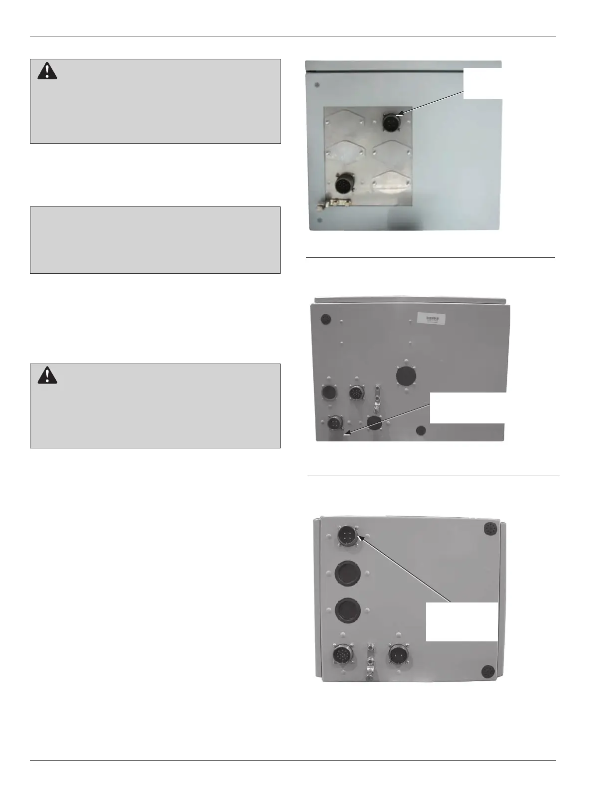
Figure 18.
Form 6 control Voltage Sensor receptacle.
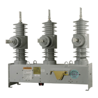
Figure 17.
Form 5 control Voltage Sensor receptacle.
CAUTION: Equipment misoperation. Do not con-
nect this control to an energized recloser until
all control settings have been properly programmed
and verified. Refer to the programming information for
this control. Failure to comply can result in control and
recloser misoperation, equipment damage, and per-
sonal injury. G110.3
CAUTION: Equipment misoperation. Verify all connector
pins and both mating interface surfaces are clean and
dry before connecting cables. Voltage sensing errors can
result from contamination. Failure to comply can result in
control and recloser misoperation. G142.0
Figure 16.
Form 4D control Voltage Sensor receptacle.
CAUTION: Hazardous voltage. Do not touch the
receptacle connections of the control/voltage-sens-
ing cable. If the recloser is energized and the control/
voltage-sensing cable is disconnected from the recloser
or the control, a voltage clamped at 250 VAC will be pres-
ent at the receptacle. Contact with this voltage can result
in personal injury. T346.1
Internal Voltage
Sensor Receptacle
Internal
Voltage Sensor
Receptacle
Internal Voltage
Sensor Receptacle
 Loading...