M750 and M800 Installation Instructions 13
1313
13
that slides into slots shown in Figure 1. The switch
enables the system to generate a tamper alarm if
the lid of the control panel is removed or if the control
panel is removed from the wall.
Factory Restart Connector
("18" in Figure 2.)
If the pins of the FACTORY RESTART connector are
shorted during power-up, all system parameters are
reset to their factory default settings, including the
engineer passcode, as documented in the
Engineering Manual.
Ensure that the terminals remain shorted until the
heartbeat LED (LED1) flashes.
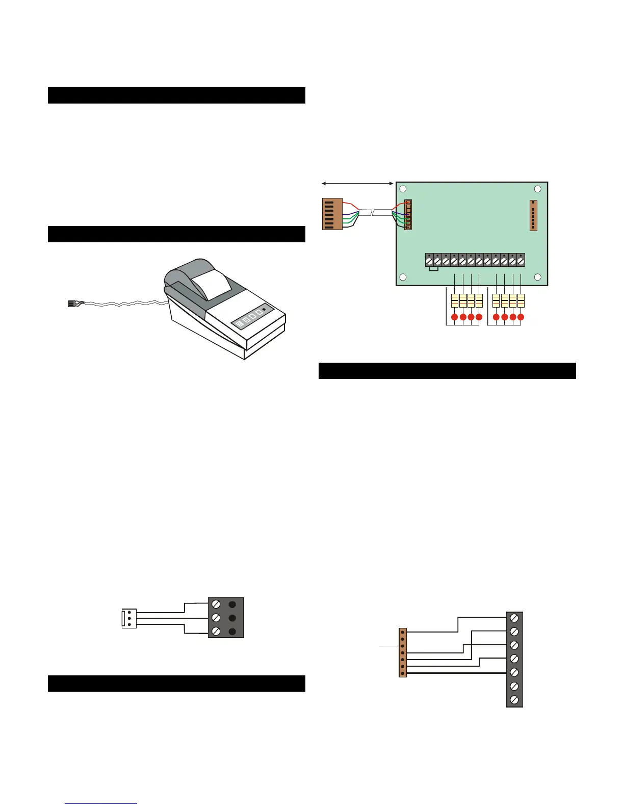
Serial Printer Connector
("19" in Figure 2.)
Serial printer
(e.g. DATAC)
RS232 Data
Connect to
control panel
Figure 15: Using a Printer
The SERIAL PRINTER connector enables a serial (RS232)
printer to be connected directly to the control panel,
such as a DATAC printer (part number 947UK-00).
Connection details are shown in Figure 16.
The printer can, for example, be used to:
• Produce a hardcopy record of system
programming details.
• Print logged events. The system can be
configured to enable online printing, where
logged events are automatically printed as they
occur.
The printer must be set up with the following
communication settings: 4800 baud, eight data bits,
one stop bit, one start bit, no parity and DTR normal.
0V
DTR
Tx
Printer
Serial printer
connector on
control panel
Figure 16: Printer Connections
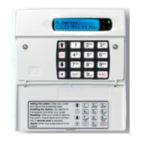
Output Module Connector
("20" in Figure 2.)
CPA6 output modules can be connected to the
OUTPUT MODULE connector to provide eight
additional 100mA switched-negative programmable
outputs per module. The outputs can be used to
drive LEDs or other low-power devices (see Figure 17).
Each output module is supplied with an interface
lead, which enables easy connection to the control
panel (or to an XNode or MNode).
When the output module is connected to the control
panel, the outputs can be programmed to indicate
ward status or zone alarms.
For further details, please refer to the CPA6 Output
Module Installation Instructions.
PL1
1k Resistors
LEDs
1234 567
+12V IN
+12V OUT
+12V OUT
8
PL2
Connect to plug
labelled OUTPUT
MODULE
100m max.
Figure 17: Output Module Connections
Engineer Keypad Connector
("21" in Figure 2.)
A keypad set with its ID selector switch set "ENG" can
be connected directly to the ENGINEERS KEYPAD
connector on the control panel, using the Engineer
Keypad Interface (EKI) lead. (Figure 18 provides
connection details.)
An engineer's keypad is intended to be temporary
connected to the control panel for system
configuration and testing at the control panel. The
keypad can be disconnected without causing an
alarm. Once a system has been set up, system
configuration should normally be carried out from a
keypad attached to Network 1 or 2.
The zone and output terminals on an engineer's
keypad cannot be used.
A