M750 and M800 Installation Instructions 9
99
9
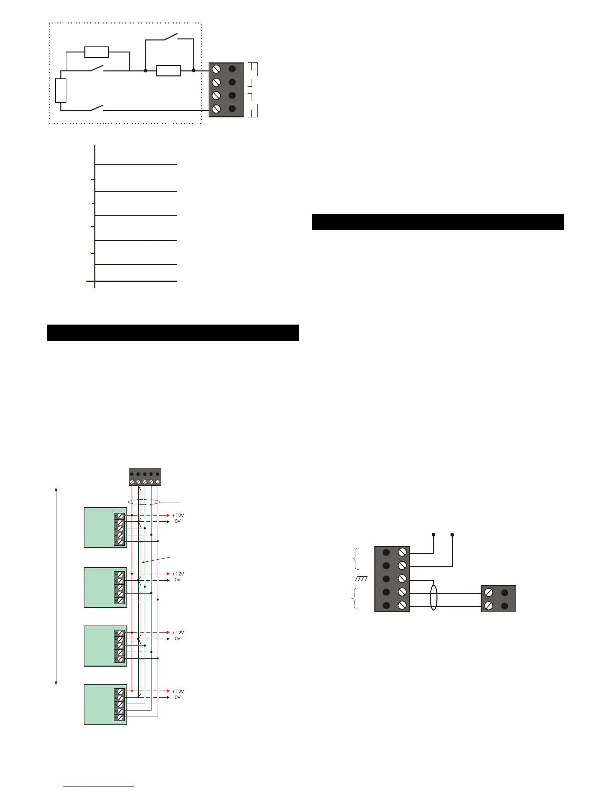
CIRCUIT 2
Z2 T2
2K2
2K2
4K7
Tamper
Alarm
Short Circuit Tamper Alarm
Open Circuit Tamper Alarm
Zone
Resistance
Healthy
Masked
Masked
Alarm
9.1k
2.2k
4.4k
6.9k
Anti-mask
Figure 6: Anti-Masking Zone Wiring
Network Connections
Network 1 Connections
Network 1 ConnectionsNetwork 1 Connections
Network 1 Connections
("2" in Figure 2.)
Network 1 can support up to eight zones, provided by
a combination of keypads and LEC2s (2 zones each),
connected in a star or daisy chain configuration.
Connection details are shown in Figure 7. No other
devices can be connected to Network 1.
Please refer to the device's Installation Instructions.
Control Panel Network
Spare core used to double
up "B" to reduce voltage
6 Core
Alarm Cable
Power for
detectors
Power for
detectors
Power for
detectors
Power for
detectors
I/D=2
I/D=1
I/D=3
I/D=4
Remote
Keypad
A
B
C
D
E
Remote
Keypad
A
B
C
D
E
Remote
Keypad
A
B
C
D
E
Remote
Keypad
A
B
C
D
E
ABCDE
100
x.)
Figure 7: Keypad Connections
Network 2 Connections
Network 2 ConnectionsNetwork 2 Connections
Network 2 Connections
("3" in Figure 2.)
Network 2 can connect to one of the following (see
Figure 3):
• A combination of up to three keypads and/or
LEC2s. Wiring is the same as in Figure 7.
• One ID Node. Please refer to the ID Node
Installation Instructions for connection details.
• A maximum of three XNodes or MNodes. Please
refer to the XNode\MNode Installation Instructions
for connection details.
Note: XNodes or MNodes must not connect directly
Note: XNodes or MNodes must not connect directlyNote: XNodes or MNodes must not connect directly
Note: XNodes or MNodes must not connect directly
to the same network as a keypad, LEC2 or ID Node.
to the same network as a keypad, LEC2 or ID Node.to the same network as a keypad, LEC2 or ID Node.
to the same network as a keypad, LEC2 or ID Node.
Telephone Connections
("4" and "5" in Figure 2.)
An M800 contains a built-in modem (not available on
M750). This enables direct connection to a PSTN
telephone network or PABX exchange.
This allows the system to be controlled and monitored
from a remote PC running the Downloader software,
and enables alarm status information to be
transmitted to an Alarm Receiving Centre.
You can connect an M800 control panel to a
telephone network using either of the following:
• The RJ11 telecom socket (labelled "5" in Figure 2).
Use only a pre-manufactured and approved
cable between the RJ11 socket and telephone
outlet socket.
• The PSTN terminal block (labelled "4" in Figure 2).
Connection details are shown in Figure 8. Do not
Do notDo not
Do not
make any other connections to the telephone
make any other connections to the telephonemake any other connections to the telephone
make any other connections to the telephone
network.
network.network.
network.
A
B
B1
Optional connection to only one other item
of equipment (e.g. fax or answer machine).
While the control panel is communicating,
any device connected to the "Diverted Line"
is automatically disconnected.
Ensure polarity
is correct.
Use cable type
1/05mm CW1308
BT Master Box
(Exclusive line)
Control Panel
Diverted
Line
Primary
Line
2 or B
A1
5 or A
Figure 8: PSTN Connections
The control panel is not suitable for connection as an
extension to a payphone or to "1+1" carrier systems.
The control panel has a Ringer Equivalence Number
(REN) of 0.2. For any one line, the sum of REN values
should not exceed 4.