8
88
8 M750 and M800 Installation Instructions 497139 Issue 3
Zone Wiring
("1" in Figure 2.)
The control panel has a set of eight on-board
terminal blocks for the connection of alarm sensors,
such as door contacts and PIR detectors.
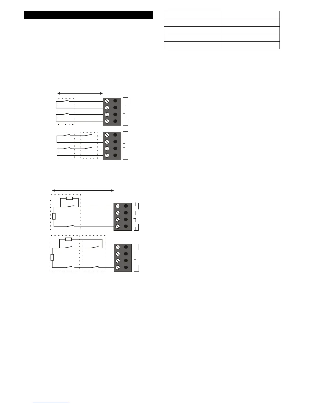
Each terminal block can connect to one or more
sensors, wired using either the double-pole (also
known as Closed Circuit Loop, CCL) method (see
Figure 4) or Fully Supervised Loop (FSL) method (see
Figure 5).
100 Ohms
Max. 10 devices per circuit
Alarm
Tamper
Alarm
Tamper
Alarm
Tamper
CIRCUIT 1
Z1 T1
CIRCUIT 2
Z2 T2
Figure 4: Zone Wiring (Double Pole/CCL)
100 Ohms
Alarm
Tamper
4K7
2K2
Max. 10 devices per circuit
Alarm
Tamper
Alarm
Tamper
4K7
2K2
CIRCUIT 1
Z1 T1
CIRCUIT 2
Z2 T2
Figure 5: Zone Wiring (FSL)
By default, alarm contacts are normally closed.
Zones with normally-open contacts must be
programmed with the "Inverted" attribute set.
The FSL method uses resistors at the end of the line
and across the alarm contact, which enables the
cables to be supervised for short-circuit or open-
circuit conditions to guard against cable tampering.
The resistors can have the values shown in Table 1
(the values used must be specified when
programming the zone).
Alarm Shunt Resistor
Alarm Shunt ResistorAlarm Shunt Resistor
Alarm Shunt Resistor End-of-Line Resistor
End-of-Line ResistorEnd-of-Line Resistor
End-of-Line Resistor
4K7 2K2
1K0 1K0
4K7 4K7
2K2 2K2
Table 1: Resistors for Zones Wired using the FSL Method
When using the FSL method, two cores are used for
each zone. When using the double-pole method,
four cores are used.
It is recommended to use only one detector per
zone, otherwise when an alarm or tamper condition
arises, the source of the alarm/tamper is not known.
If you are powering devices such as PIR detectors
from the control panel, an additional two cores are
required for connection to the 12Vdc power output
terminals (labelled "16" in Figure 2).
Whichever method is used, the wiring resistance must
be less than 100 Ohms (with the end-of-line resistor
shorted in the case of the FSL method).
If you are not using a zone, you should program the
zone as "Not Used".
Anti-Masking Zone Connections
Anti-Masking Zone ConnectionsAnti-Masking Zone Connections
Anti-Masking Zone Connections
Some PIR detectors are fitted with an anti-masking
facility to detect cases where the detector has been
obscured. Depending on the type of detector, the
masking status is conveyed by one of two methods:
• By an open/closed contact wired to a separate
zone programmed as type "Masking". Two zones
are therefore needed: one for the masking status
and the other for alarm/tamper status.
The sensor can connect using the double-pole
or FSL method. If double-pole is used for the
Masking zone, the zone's tamper terminals must
be shorted at the panel.
• By a specified resistance value to a zone (e.g.
Normal Alm or 24 Hour). The zone must be wired
as shown in Figure 6, which also shows the
resistance values used to convey the normal,
alarm, masking and tamper status.