6
66
6 M750 and M800 Installation Instructions 497139 Issue 3
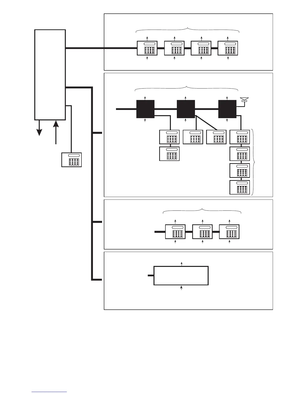
Network 1
Network 2
800 or 750
CONTROL
PANEL
3 Outputs
8 Zones
6 Outputs
24 ID Zones
Network2-Wiring Option 3
ID Node
Network Wiring=4Core
(6 core if keypad is used)
Only one ID Node
can be connected
(configured to address
nodes 1, 2 and 3)
ID Node
Network2-Wiring Option 2
Remote Keypads/LEC2s
Max 3
Network Wiring = 6 Core
Network 1 (Supports only remote keypads and LEC2s)
Engineer’s keypad
(cannot have zones
or outputs)
Max 4
100m max to
furthest
keypad/LEC2
1 Output
2 Zones
1 Output
2 Zones
1 Output
2 Zones
1 Output
2 Zones
NOTE:
Do not connect an
XNode/MNode to the
same network as an ID
Node or keypad
Network2-Wiring Option 1
XNodes and/or MNodes
An XNode/MNode is
able to drive 4 Remote
Keypads and a
Loudspeaker
100m max
100m max to
furthest keypad
300m max
to furthest
XNode/
MNode
Network Wiring=4Core
2 Outputs
8 Zones 8 Zones
Max 3
8 Zones
Max 4
2 Outputs 2 Outputs
XNode/
MNode
1
XNode/
MNode
2
XNode/
MNode
3
100m max
1 Output
2 Zones
1 Output
2 Zones
1 Output
2 Zones
100m max to
furthest
keypad/LEC2
Network Wiring = 6 Core
Figure 3: Overview of Network Wiring Options
Note:
Note:Note:
Note:
• Using a Networker Interface Board (NIB) (with power supply) enables the maximum distance from a control panel to an ID Node or keypad to be
increased to 1km.
• The supply voltage at each Network 1 or 2 device must not drop below 10.5V (recommended to be at least 12V). Refer to the Engineering Manual
for details of how to calculate and overcome voltage drops.
• Direct connection of an LEC6 (6-zone) expander to Network 1 or 2 is supported for existing systems that are being upgraded. Ensure that the
number of zones does not exceed the number that would be provided by keypads alone.