AUXILIARY POWER FOR
ACCESSORIES
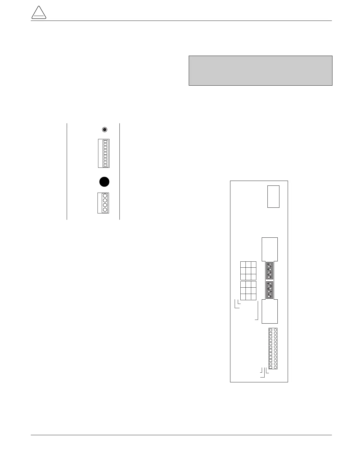
Connection P9 (Figure 20) on the Power Supply module
provides 28Vdc (12Vdc is available) to power radio com-
munication units, RTUs and other accessories. The auxil-
iary power provides 40W peak load capability. Auxiliary
power is fused at 1 Amp (F1) and current-limited to pre-
vent user loads from disabling the control.
Customer 28V connections for auxiliary power are made
to terminals 3 and 1 and are continuously energized. Ter-
minal 2 and 4 are not used at this time.
RECLOSER INTERFACE (RIF)
MODULE CONFIGURATION
The Recloser Interface (RIF) Module accepts either 12,
120, or 240 Vac voltage inputs for metering. The RIF Mod-
ule is factory-configured at 120 Vac. The available volt-
ages and their settings are indicated on the operator
panel of the RIF module. Two sets of dip switches, located
on the RIF operator panel, utilize different switch positions
to configure the desired voltage. See Figure 21.
Configure the RIF board by positioning the dip switches to
the desired voltage setting.
Reference the voltage table next to the switches. The
ON position is to the left; the OFF position is to the right
(Figure 21).
S280-42-3
21
CAUTION: Equipment damage. Always wear a ground-
ing wrist strap to control static electricity before handling
circuit boards. Failure to use this strap may result in cir-
cuit board damage. T253.1