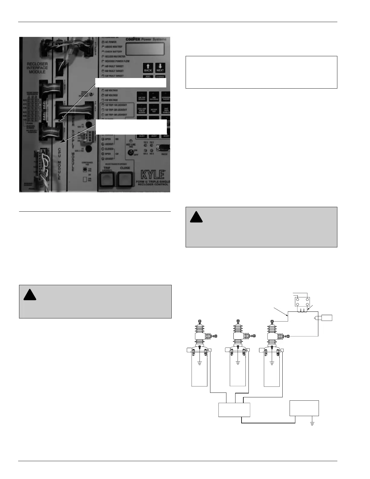
Check CPU Status
Check the operating status CPU module. Open the cabi-
net door and locate the LED indicator (see Figure 41).
The LED indicator on the CPU module should flash at a
rate of one flash per second for normal operation.
Electrical Testing of NOVA-TS
Triple-Single Reclosers
Each unit in the Type NOVA-TS Triple-Single recloser uti-
lize an interface circuit located in its mechanism housing.
The electronic interface circuit controls the opening and
closing signals to the magnetic actuator.
Figure 42 shows a test circuit for NOVA-TS reclosers with
the Form 5/Triple-Single control.
Use this circuit to simulate load current and for testing
minimum trip operation and sequencing the mechanism
with the Form 5/Triple-Single control for each phase.
Remove the Control from
Service
1. Enable GND TRIP BLOCKED to allow for ground trip
to be disabled when re-energized.
A. Press the CHANGE/LAMP TEST key on the Oper-
ator Panel to enter the CHANGE mode.
Note: The LCD Display Screen will indicate the amount
of time available in CHANGE mode to make a
change.
B. Depress the GND TRIP BLOCKED key.
Note: After the GND TRIP BLOCKED key is
depressed, the red LED indicator will illuminate
to indicate GROUND TRIP BLOCKED is active.
2. Unplug the control battery.
3. Remove control ac sensing and power connections
from the control using a separate disconnect switch.
4. Disconnect control cable from the control.
5. Disconnect the ground from the control.
Kyle Form 5/Triple-Single Microprocessor-Based Recloser Control Installation and Operation Instructions
42
WARNING: Hazardous voltage. Solidly ground
all equipment. Failure to comply can result in
death, severe personal injury, and equipment damage.
T223.2
Figure 41.
Form 5/Triple-Single control CPU module.
99016KM
CPU Module
(Central Processing Unit)
CPU Module LED Indicator
IMPORTANT: Disconnect switches for ac sensing
and power connections are necessary to isolate the
Form 5/Triple-Single Recloser Control for testing and
servicing.
WARNING: Hazardous voltage. If the recloser
is energized while the control cable is discon-
nected, the CT secondaries can generate high volt-
ages. Contact with high voltage can cause severe
personal injury or death. T204.2