Form 5/Triple-Single Control
Operator Panel
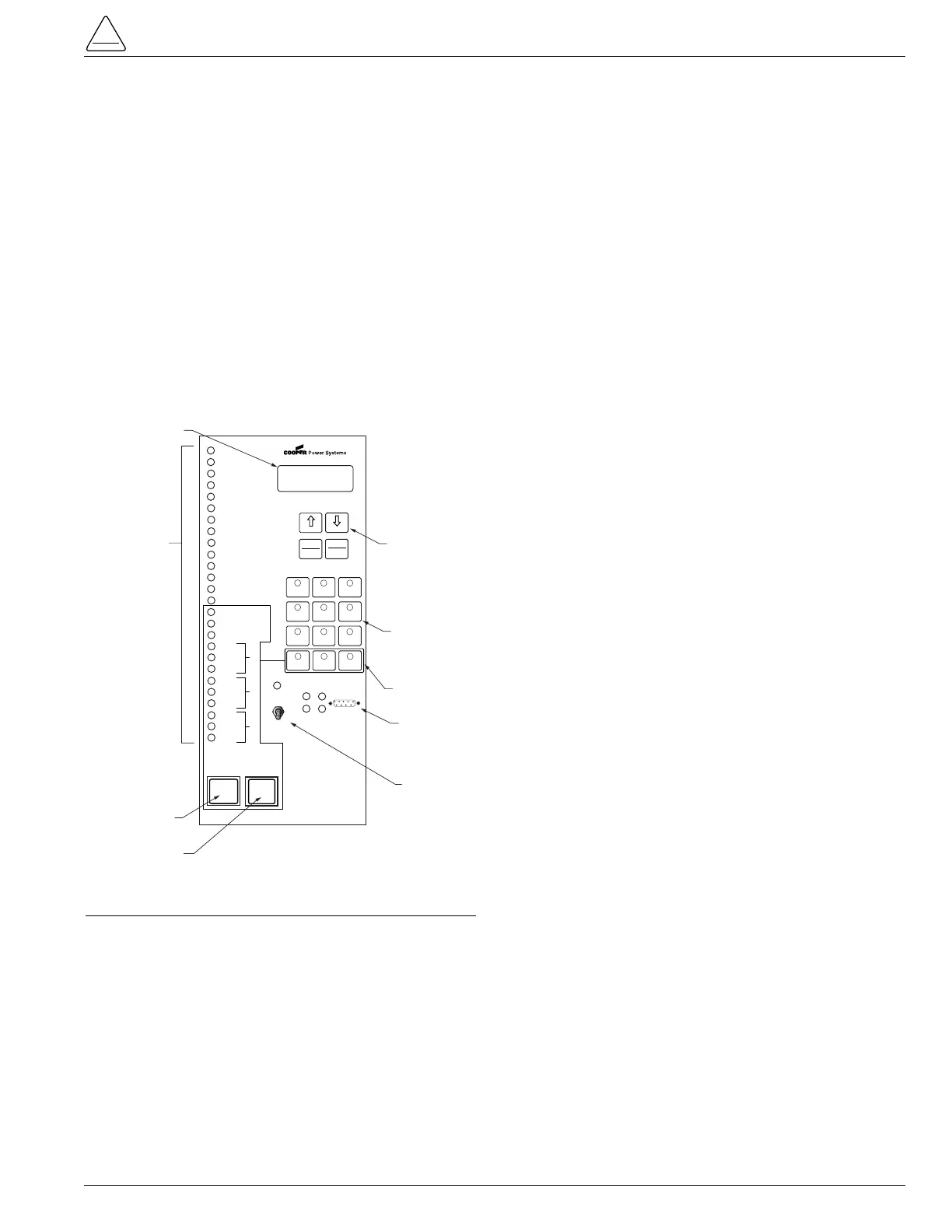
The Form 5/Triple-Single control operator panel (Figure 5)
allows local operation and status interrogation through
built-in operator controls and status displays. The opera-
tor panel contains LED indicators, operational pushbut-
tons, membrane-type functional/indication switches,
backlit LCD display, and Hot Line Tag switch with indica-
tion. An RS232 port is also provided to permit the tempo-
rary connection of a personal computer for programming
the parameters in the control.
All indicators with the exception of Hot Line Tag and
recloser status are automatically turned off after 5 minutes
of operator panel inactivity. Reactivating is accomplished
by pressing any operation switch.
LED Indicators
The operator panel LED indicators (Figure 5) give instant
information on the control and recloser status.
LED indicators include:
CONTROL OK
This green LED is illuminated when the continuous self-
diagnostics of the control have detected no CPU or mem-
ory malfunctions and indicate that the control is capable of
normal operation.
AC POWER
This green LED is illuminated when the presence of ac
input power to the control is sensed. The LED will turn off
if ac power is lost for more than 15 seconds.
ABOVE MIN TRIP
This red LED is illuminated when the control detects that
current is above the programmed minimum trip value for
Bushings 1-2, Bushings 3-4, Bushings 5-6, Ground, or
Sensitive Ground.
CHECK BATTERY
This red indicator illuminates when the control fails a bat-
tery test. A failed test can indicate any of these conditions:
• The measured battery voltage is less than 22 volts.
• The battery voltage drops more than 2 volts during the
battery test.
• A battery is not in the unit or the battery is open.
The LED will remain on until a new battery is installed or
other corrective action occurs and a successful battery
test is completed. Refer to Battery Testing and Charg-
ing Procedures in the Testing section of this manual for
more information.
RECLOSER MALFUNCTION
This red indicator is illuminated when the control detects
a failure in a trip or close operation. It turns off automati-
cally if the recloser returns to the proper state.
REVERSE POWER FLOW
This red indicator illuminates when the control detects
power flow from the load side to the source side of the
recloser.
Note: Voltage sensor polarity must be correct for reverse
power flow to function properly.
AØ FAULT TARGET
BØ FAULT TARGET
CØ FAULT TARGET
GROUND FAULT TARGET
SENSITIVE GROUND FAULT TARGET
These red target LEDs illuminate when the control issues
an overcurrent trip signal while the respective phase cur-
rent or ground current exceeds the minimum pickup
value. Reset is accomplished automatically when Auto
Reset is activated and a successful close operation is per-
formed or manual reset is accomplished by pressing the
RESET TARGETS button on the control operator panel.
S280-42-3
7
NO. 1
NO. 2
NO. 3