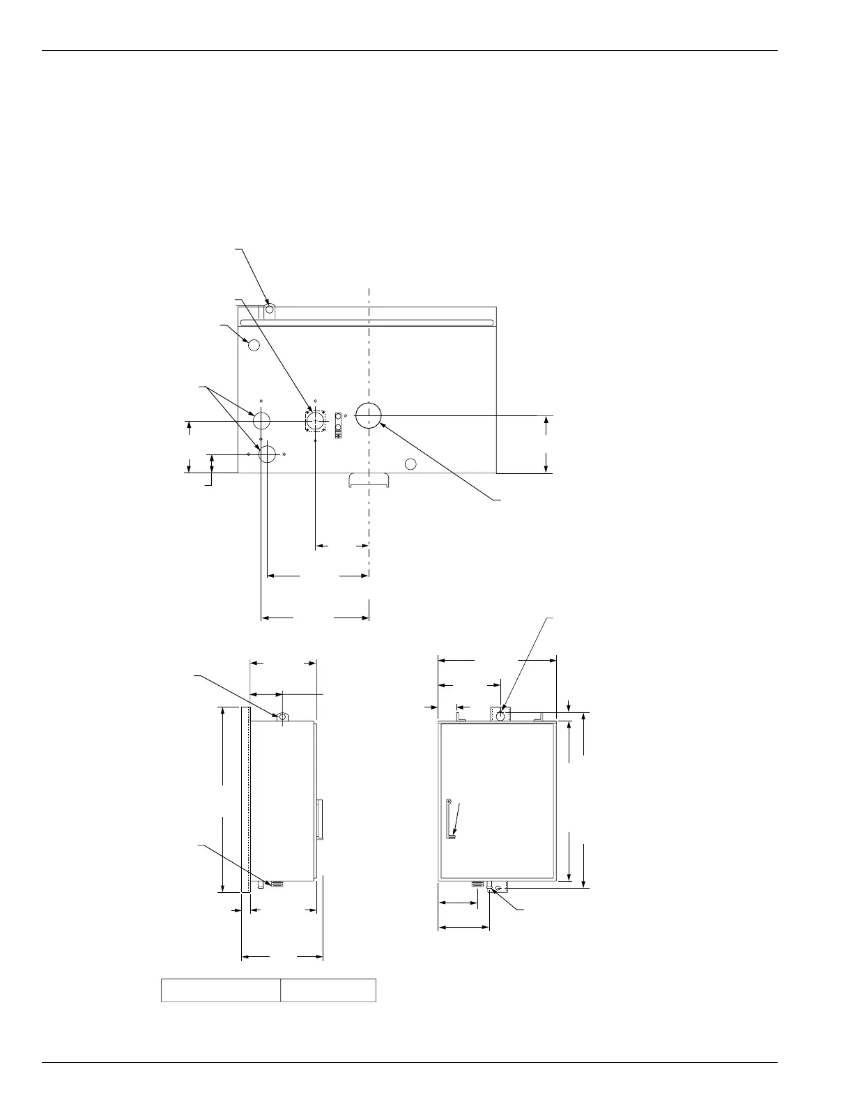
Mounting the Control
Mount the Form 5/Triple-Single recloser control in a con-
venient, accessible location. Mounting dimensions are
provided in Figure 29.
For pole-mounted installation, a hole and keyway in the
control mounting bracket accommodates a 5/8” bolt.
Limits on control cable length are determined by the max-
imum distance between the control, junction box, and
NOVA-TS Triple-Single recloser:
• Up to 312 m (95* ft) for NOVA-TS Triple-Single
recloser.
* This length is based on standard control cables. Consult
your Cooper Power Systems representative if longer
cable lengths are required.
Kyle Form 5/Triple-Single Microprocessor-Based Recloser Control Installation and Operation Instructions
32
Use No. 14 To No. 4
45mm (1-3/4") Dia. Hole
35mm (1-7/16") Dia. Hole
16 (5/8) Dia. Hole
20 (3/4) Dia. Hole