S280-30-7
11
5. Install new bushing through head.
6. Position bushing with stud end of terminal pointing outward.
7. Position clamping ring with split centered between the two out-
side clamping bolts.
8. Reassemble bushing to head casting. Tighten bolts evenly, a
little at a time, to 10-15 ft-lbs torque.
NOTE: Clamping forces must be applied gradually and equally in
rotation to each bolt. This results in an evenly distributed gasket seal-
ing pressure.
9. Reconnect lead to bushing rod.
Vacuum Interrupters
Vacuum interrupters must be replaced when:
• They lose their vacuum as evidenced by a failure during the low
frequency dielectric withstand test across the open contacts;
• The interrupter contacts have eroded beyond their useful life
as evidenced by the position of the scribe mark on the moving
contact rod; or
• The interrupters have completed their mechanical life of 7000
operations.
To replace an interrupter, refer to Figure 16 and proceed as
follows:
1. Make sure the recloser contacts are open; the yellow manual
operation handle, under the sleet hood, is pulled down.
2. Cut nylon tie straps which secure the vertical insulating barrier
and remove barrier.
3. Loosen and remove upper interrupter clamp. As the clamp is
loosened, atmospheric pressure on the bellows will cause the
contact rod to move down into the interrupter. This
action can be verified by observing the scribe mark on the
contact rod. It will move downward to just above (or below)
the fiber disk at the top of the interrupter.
NOTE: If the contact rod does not move, the interrupter may have
lost vacuum or the contact rod may be sticking in the clamping fin-
gers of the contact operating rod assembly. Use a screwdriver to
gently spread the clamping fingers to free the rod.
4. Disconnect bushing lead from lower contact plate assembly.
5. Loosen and remove lower interrupter clamp.
6. Remove hardware attaching lower contact plate to the three
vertical stringers and remove contact plate and interrupter.
7. Install the new vacuum interrupter into the clamping fingers of
the contact operating rod and the lower contact plate. Attach
the plate to the stringers.
NOTE: On side with the single stringer, a spacer on the stringer stud
provides a 1/16-inch gap between contact plate and the attaching flat
washer and locknut when the interruptercontacts are open. This gap
is intentional.
8. Manually close recloser.
9. Coat threads of interrupter clamps and attaching screws with
a film of transformer oil and loosely install.
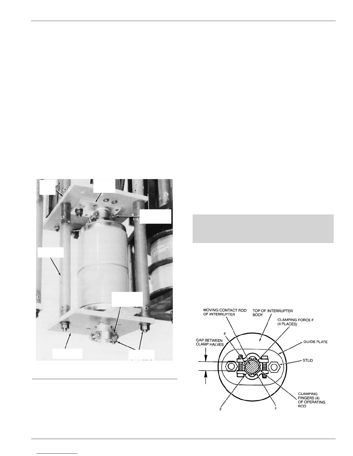
10. Rotate interrupter so that one of the hex nuts at the top of the
interrupter is centered directly beneath the gap on one side
of the upper clamp. (See Figure 17.)
11. Position the upper and lower interrupter clamps just below the
shoulder on the finger-type current exchange connectors so
clamping force will be applied to the center of each finger, as
shown in Figure 17.
CAUTION
When rotating the interrupter avoid twisting the contact rod
to prevent damaging the bellows and destroying the inter-
rupter.
12. Tighten screws of each interrupter clamp evenly to 75 in-lbs
torque
.
NOTE: Clamps must be tight to prevent slippage of interrupter con-
tact rods in their current-exchange connectors.
13. Reconnect bushing lead to lower contact plate.
14. Reinstall vertical insulation barrier plate between long bush-
ing lead and the mechanism. Position plate and secure it
and the bushing lead with nylon tie straps.
Figure 17
Orientation or interrupter and clamp.
Figure 16.
Vacuum interrupter replacement.
86787KMA
UPPER
INTERRUPTER
CLAMP
UPPER
PLATE
CONTACT
UPPER
PLATE
FIBER
SINGLE
STRINGERS
LOWER FIBER
PLATE
DOUBLE
STRINGERS
LOWER
INTERRUPTER
CLAMP