Types VW and VWV Maintenance Instructions
4
Vacuum Interrupters
Circuit opening and fault interruption is achieved within the three
sealed vacuum interrupters. The moving contact rod assemblies
are operated by the recloser mechanism to open and close the
vacuum interrupter contacts. Berylium copper garter springs are
used in the current exchange assemblies to provide a multi-point
low resistance current path between the stationary bushing leads
and the moving contact rod of the interrupters.
Closing Solenoid
The moving contacts of the interrupters are closed by the closing
solenoid, which also extends the opening springs in the head
mechanism. This solenoid is energized for only a few cycles dur-
ing each closing operation when it is momentarily connected
across phases B and C.
Closing Solenoid Contactor
Mechanically operated by the head mechanism, the snap-action
contacts of the closing coil contactor complete the high-voltage
circuit to the closing solenoid for each closing operation.
Hydraulic Pump and Lockout Piston
The hydraulic pump counts the number of times the recloser trips.
With each trip the pump piston is pushed into the pump cylinder,
oil is forced through the lockout cylinder check valve into the lock-
out cylinder. This causes the lockout piston to be raised one step.
When the recloser resets the pump piston is pulled back to the
top of the pump cylinder and oil is drawn in through the intake
check valve.
If the recloser trips again the pump piston will actuate causing
the lockout piston to be pushed up another step. This cycle will
repeat until the recloser locks out. Once locked out the quick
reset rod is mechanically raised allowing the lockout piston to
quickly resettle. If the recloser does not lockout, the lockout pis-
ton will resettle gradually (at a rate of approximately 90 seconds
per accumulated operation at 25°C).
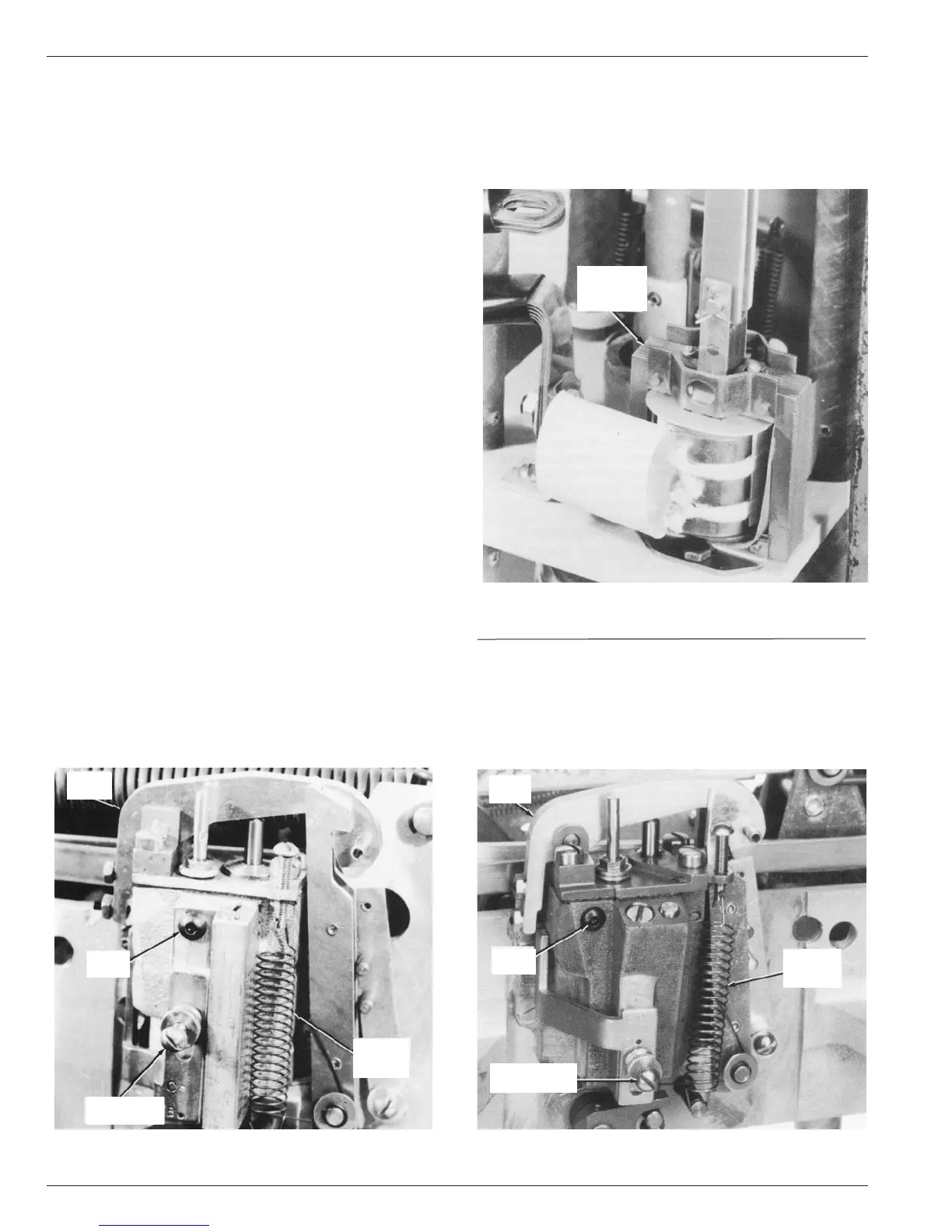
Series Trip Solenoids
The series trip solenoids (Figure 3) are connected in series with
the vacuum interrupters, each carries full line current. When line
current exceeds the minimum trip rating of a coil, by approxi-
mately 200 percent, the plunger is drawn into the solenoid. Near
the end of the plunger stroke the recloser mechanism trips.
When the recloser mechanism is sequenced to the delayed
operation phase, the speed of plunger movement is restrained
by a time-delay unit. The restrained plunger movement pro-
vides a fixed time delay before the recloser mechanism trips.
Time Delay Unit
When the mechanism is sequenced to a delayed operation the
latch assemblies of the trip solenoid plunger linkages are
engaged with the arms on the sealed time-delay units, Figure 4a
and 4b. Trip solenoid plunger movement is then restrained by the
time-delay unit, which provides a consistent delay action by forc-
ing hydraulic fluid through a calibrated orifice within the unit.
Figure 4a.
Time delay unit (old).
82020KMA
DELAY
ARM
FILLER
PLUG
ADJUSTMENT
SCREW
MINIMUM
TRIP
SPRING
Figure 3.
Series Trip coil.
84612KMA
SERIES
TRIP
SOLENOID
Figure 4b.
Time delay unit (new).
86780KMA
FILLER
PLUG
DELAY
ARM
MINIMUM
TRIP
SPRING
ADJUSTMENT
SCREW