Types VW and VWV Maintenance Instructions
12
15. Manually trip and close the recloser several times to check
interrupter operation.
NOTE: Contact movement can be verified by observing the move-
ment of the scribe mark on the upper contact rod of the interrupter.
When the recloser is open the scribe mark will be about 5/8-inch
above the fibre disk; on closing the mark will travel 1/2-inch down-
ward.
Closing Solenoid Contactor
If the contacts are badly burned or eroded, the entire contactor
must be replaced. See Figure 18 and proceed as follows:
1. Unhook the two toggle springs from the pin that connects the
operating shaft of the contactor to the toggle arm.
2. Remove the C-type retaining rings and withdraw the toggle
pin.
3. Disconnect the two coil leads from the contactor.
NOTE: Reattach the lockwasher and hex nut to the contactor termi-
nal immediately after disconnecting the coil lead to prevent loss of
moving contact parts which are attached to the support plate with the
same hardware.
4. Disconnect the two fuse leads from the contactor.
5. Remove three hex head capscrews and lockwasher that
attach the contactor to the underside of the recloser mecha-
nism frame and remove contactor.
6. Install new contactor by reversing the disassembly procecure.
Use new C-rings to secure the toggle-link pin.
7. Connect solenoid coil leads to lower terminals.
8. Connect fuse leads to upper terminals.
NOTE: Be sure coil and fuse leads are positioned for maximum clear-
ance to grounded parts.
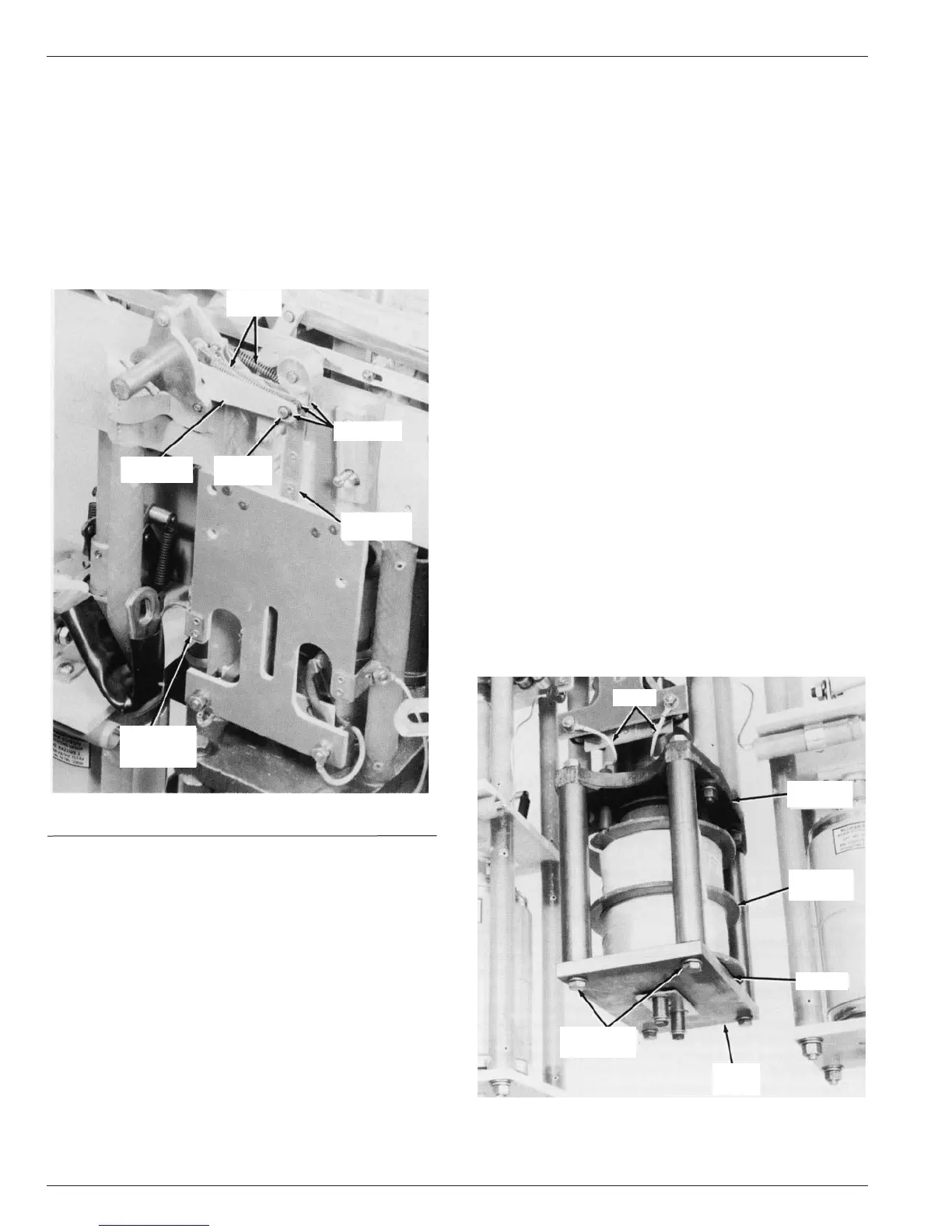
Closing Solenoid
The closing solenoid coil is connected phase-to-phase and is
rated to operate at full system voltage. It is protected with two
fuses, one on either side. A data plate attached to the recloser
head between source side bushings 3 and 5 provides the coil
connection information. If the solenoid coil must be replaced, due
to damage or
change in operating voltage, refer to Figure 19 and proceed as
follows:
1. Disconnect the two coil leads from closing solenoid contactor.
NOTE: Reattach the lockwashers and nut to the contactor terminal
immediately after disconnecting the coil lead to prevent loss of parts
of the moving contact arm assembly which is attached to the support
plate with the same hardware.
2. Remove four capscrews and lockwashers which attach base
plate to bottom of solenoid frame posts and lower coil and
base plate.
3. Remove coil from the base plate and discard coil gasket.
4. Using a new coil gasket, install new closing coil on the base
plate.
NOTE: A new coil gasket is included in the closing coil replacement
kit.
5. Reassemble base plate to solenoid frame posts and connect
coil leads to the contactor terminals. Make sure the coil leads
clear the solenoid frame by at least 1/2-inch.
6. The closing coil replacement kit includes two new coil fuses
which should be installed with the new coil.
7. The closing coil replacement kit also includes a new voltage
date plate. Replace the plate on the sleet hood of the recloser
head if the operating voltage of the recloser is being changed.
NOTE: VWV27 reclosers, with 20 kv closing coils, above serial num-
ber 975 have a rigid tube insulator on the long coil lead. 20 kv and
above replacement coils for units below serial number 975 include
additional parts to modify the solenoid assembly to accommodate the
rigid insulating tube. Installation instructions are included with the kit.
Figure 19.
Parts involved in solenoid coil replacement.
86784KMA
LEADS
SOLENOID
FRAME
HEX HEAD
CAPSCREWS
GASKET
BRIDGE
PLATE
SOLENOID
COIL
Figure 18.
Replacing closing coil contactor.
84614KMA
TOGGLE
SPRINGS
C-RINGS (4)
OPERATING
LINK
TOGGLE
PIN
TOGGLE
MECHANISM
CLOSING
SOLENOID
CONTACTOR