S280-30-7
13
SERIES TRIP SOLENOID
The continuous current rating and the trip current rating of the
recloser can be changed by installing new coils in the series trip
solenoids. Tripping occurs at about 200% of the continuous cur-
rent rating of the standard coil and at about 140% when the alter-
nate (400X or 560X) coils are used. The maximum interrupting
rating of the recloser is dependent upon the continuous current
rating of the series trip coil.
Two different coil replacement kits are required. One for Phase A
and Phase B solenoids and another for Phase C (the interrupter
furthest away from the sleet hood) which has an opposite wind
because it mounts differently on the interrupter. The same basic
replacement procedure is used for either type coil.
Solenoid Disassembly
1. Remove cotter pin; slide out the groove pin and spacer that
connect the insulated operating links to the solenoid plunger
(Figure 20).
2. Remove bolt that fastens both the outer coil terminal and the
short bushing lead to the lead mounting bracket.
3. Remove the capscrew that connects the inner coil terminal
strap to the interrupter current interchange.
4. Remove elastic stop nut and flat washer that secure solenoid
frame to the upper current exchange mounting board. Lift
entire solenoid assembly off board.
5. Remove solenoid plunger, guide clips, guide channels and
upper coil washer.
6. Lift coil slightly and pull out of the solenoid frame.
7. Replace any damaged parts at this time.
Solenoid Replacement
Check lower coil washer before installing new coils. For coils
rated 280 amperes and below the upper and lower coil washers
are identical. For 400 and 560 ampere rated coils, the lower
washer requires a larger center slot. The same upper washer is
used with all coil sizes.
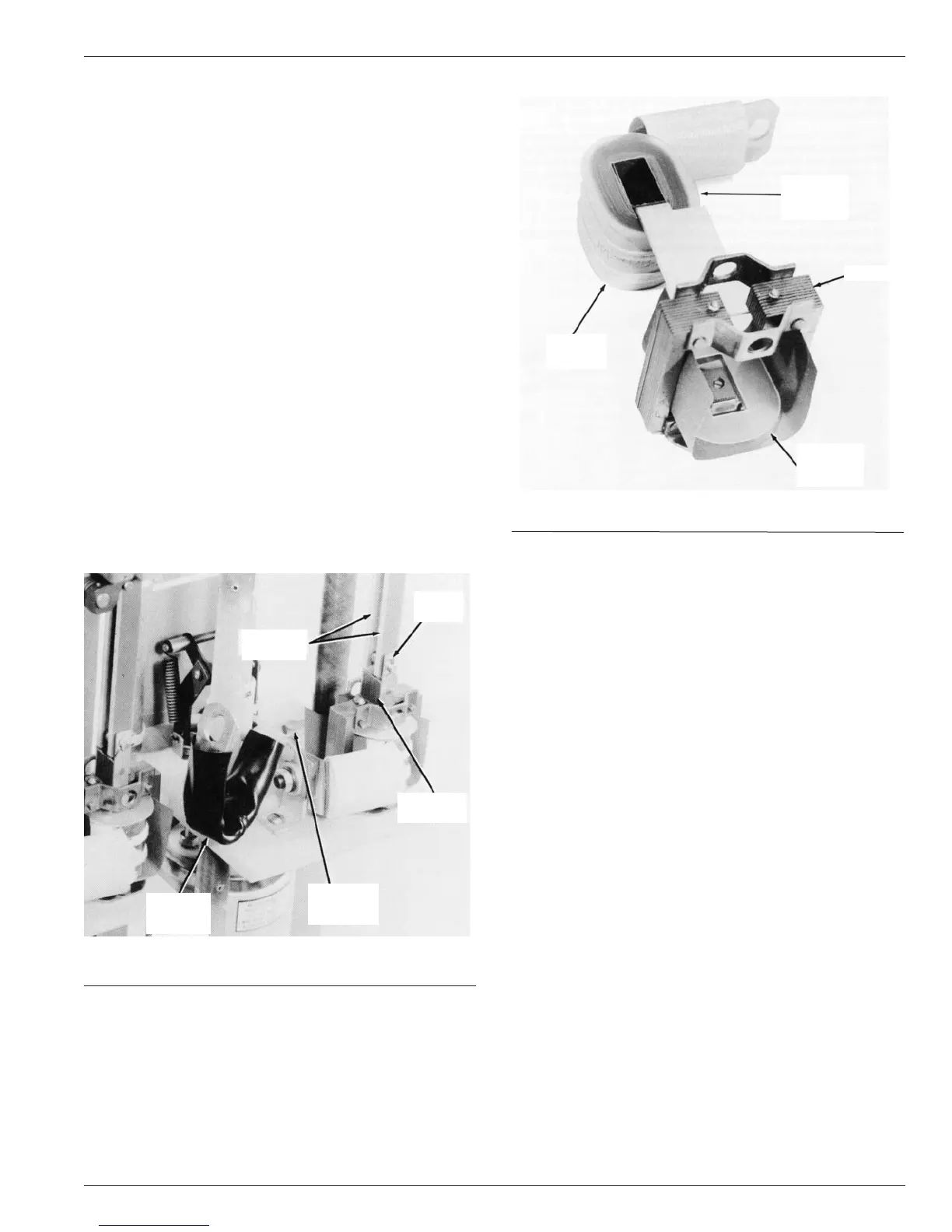
1. Pass upper insulating washer over terminal strap and align its
slot with the coil slot (Figure 21).
2. Insert coil into the frame and slide the upper coil washer into
position.
3. Replace in order the guide channels, guide clips and plunger.
4. Place the solenoid assembly back on the mounting board
and secure it with the flat washers and elastic stop nuts.
5. Connect operating links to the solenoid plunger with the
groove pin, spacer and cotter pin.
6. A sleeve is provided with each coil to insulate the outer coil
lead from the frame. Slide the lead over the outer lead as ill-
lustrated.
7. Connect the coil terminals to the current interchange and the
bushing lead to complete the assembly.
TIME DELAY UNIT
The recloser is equipped with hydraulically-operated time delay
units on each phase. These provide the different time-current
characteristic (TCC) curves, as shown in Reference Data
R28091-6. Each unit can provide either of two-time delay char-
acteristic curves, but not all four (KA1 194R1 provides B and C
curves and KA1194R2 provides D and E curves).
When the mechanism is sequenced to the delayed operation
phase, the latch assembly of the trip-coil plunger linkage is
engaged with the arm of the time-delay unit, this provides con-
sistent delay action by forcing hydraulic fluid through an orifice in
the unit. Special aircraft-type fluid is used to minimize tempera-
ture effects.
Maintenance
Maintenance to the time delay units is limited to checking the fluid
level in the units. Some loss of fluid is normal, therefore this
inspection should be made each time periodic maintenance is
performed.
To check the fluid level, remove the socket-head filler plug
located on the side of the unit. Add enough fluid to bring the level
up to the filler plug hole. Avoid introducing dirt, lint or any other
foreign material when filling the unit as this can plug the orifice
and cause erratic time-delay action.
NOTE: A special fluid replacement kit, catalog number KA806R2, is
available. The kit consists of approximately 60 cc (2 US fl. oz. ) of the spe-
cial hydraulic fluid in an eye-dropper bottle.
Figure 20.
Series trip solenoid removal.
84613KMA
OPERATING
LINKS
COTTER
PIN
SOLENOID
PLUNGER
INNER COIL
TERMINAL
BOLT
SHORT
BUSHING
LEAD
Figure 21.
Assembling solenoid series trip coil.
82023KMA
SOLENOID
COIL
UPPER
INSULATING
WASHER
FRAME
LOWER
INSULATING
WASHER