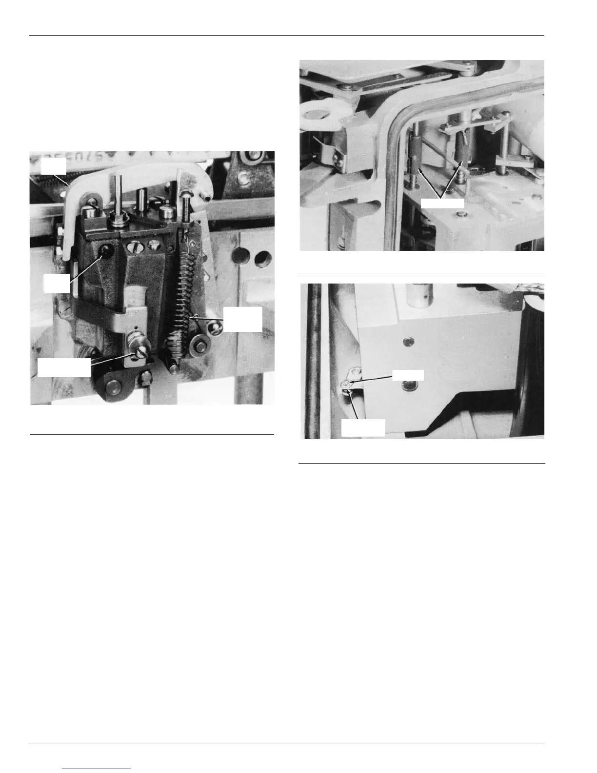
Figure 24.
Remove E-ring to disconnect auxiliary switch operating lever.
Types VW and VWV Maintenance Instructions
14
Replacement
Replacement time-delay kits include a factory calibrated time
delay, four flat head screws and a minimum-trip calibration
spring. Remove the malfunctioning unit and install the replace-
ment in its place (see Figure 22).
The minimum trip setting of the recloser must be recalibrated
by adjusting the spring tension whenever a new time-delay unit
is installed.
Removing Mechanism from Head
To gain access to components located in or on the main frame,
the following procedure may be used to remove the mechanism
from the head.
NOTE: These procedures will be simplified if the untanked head and
mechanism assembly can be inverted (bushings down). The unit can be
supported on its bushings.
1. Disconnect all six bushing leads from the ends of the bush-
ings.
2. Disconnect the lockout lever and contact position indicator
shafts by disengaging the spring loaded couplers and locking
them in the disengaged position, Figure 23.
3. Disconnect any accessories, such as a ground trip solenoid,
at their terminals.
4. If the recloser is equipped with the auxiliary switch accessory,
remove the C or E-ring and washer, Figure 24, and discon-
nect the operating lever of the switch from the recloser mech-
anism.
5. Remove the six socket head bolts and lockwashers that
secure the frame to the head casting and carefully lift the
mechanism from the head. Six long pipe spacers will be
released when the mechanism is lifted.
NOTE: By temporarily substituting eye-bolts for two of the hex head
bolts in the bottom of the closing solenoid frame, the mechanism can
be easily lifted and handled with a hoist.
6. Remove couplers from contact position indicator and lockout
lever shafts.
Reinstalling Mechanism into Head
To reinstall the recloser mechanism assembly into the head, the
following procedure may be used.
1. Install the couplers on the lockout lever and contact position
indicator shafts. Lock them in the disengaged position.
2. Carefully lower the mechanism assembly onto the six pipe
spacers which have been positioned over the mounting holes
in the casting.
3. Install the six socket head bolts and tighten evenly to avoid any
binding of the mechanism.
NOTE: Replace the hex head bolts in the bottom of the closing
solenoid frame if eye-bolts were used for handling the recloser
mechanism.
4. Re-engage the lockout lever and contact position indicator
shaft by releasing the shaft couplers.
5. Reconnect the operating lever of the auxiliary switch (if used)
to the mechanism and secure with the washer and E-ring
(Figure 24).
6. Reconnect the bushing leads to the end of the bushings.
TESTING
Procedures for testing the Type VW, VWV27 and VWV38
reclosers are included in the Installation Manual S280-30-1.
Figure 22.
Remove and replace time delay.
86780KMA
MINIMUM
TRIP
SPRING
ADJUSTMENT
SCREW
FILLER
PLUG
DELAY
ARM
Figure 23.
Disconnect couplers.
84605KMA
COUPLERS
83375KMA
E-RING
OPERATING
LEVER