S280-30-7
5
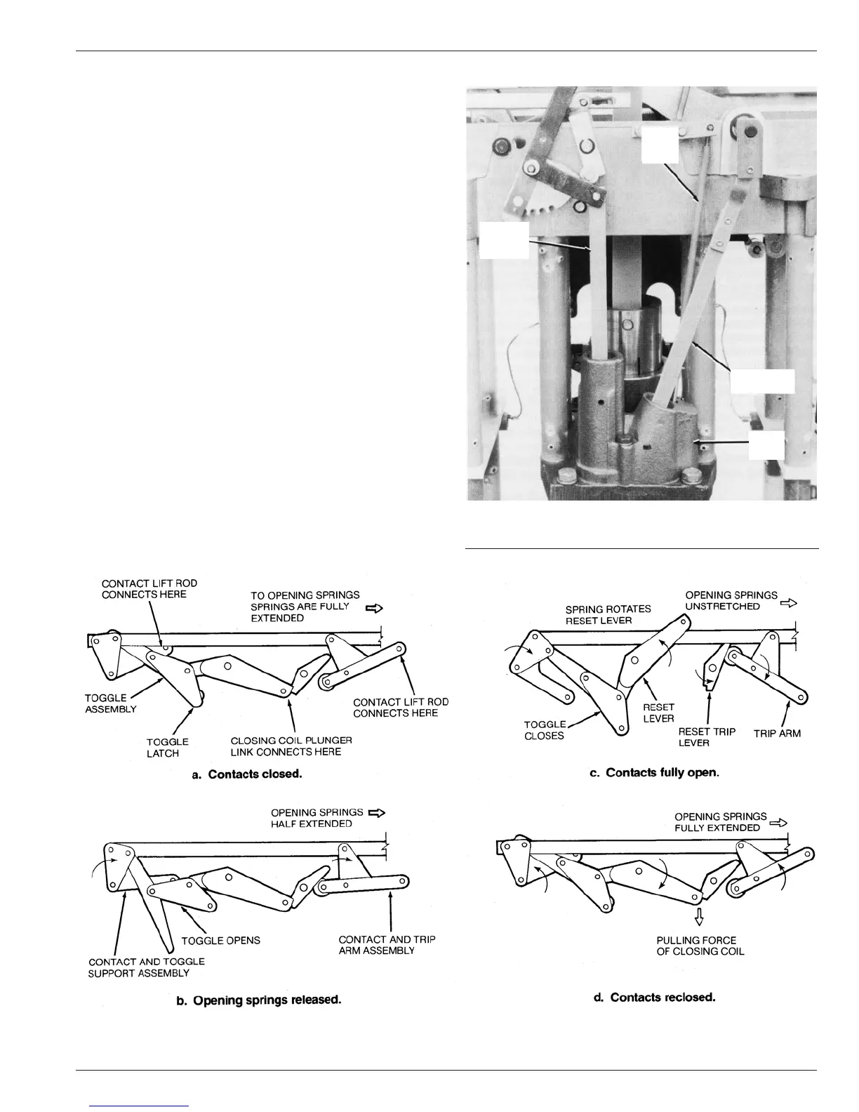
Figure 5.
Head mechanism lever arrangement
MECHANISM OPERATION
The operating mechanism, mounted in the head, opens and
closes the vacuum interrupter contacts. Contact opening is initi-
ated by a series trip solenoid which triggers the trip mechanism
to release the loaded opening springs. Contact closing is per-
formed by the closing solenoid which also charges the opening
springs and resets the mechanism for the next trip operation.
The basic operation of the mechanism is shown in Figure 5.
With the interrupter contacts closed (a), the opening springs
are fully extended and the mechanism is in the reset state. When
excessive current levels are passing through the series trip coil
the solenoid plunger is actuated. The trip solenoid plunger oper-
ates the toggle latch, releasing the toggle. This action releases
the opening springs (b) which starts the contact bar assembly in
motion. The spring-biased reset lever rotates to snap the toggle
closed. This action of the reset lever also pulls the plunger out of
the closing solenoid. At this point the interrupter contacts are
fully open (c) and the mechanism is in the open state. When the
closing solenoid plunger reaches the top of its stroke it mechan-
ically closes the closing coil contactor which energizes the clos-
ing solenoid. As the plunger is drawn down into the coil the reset
lever is pulled back and latched in its original position. The inter-
rupter contacts are closed (d) and the opening springs are
extended. The mechanism is now ready for another opening
operation.
HYDRAULIC CONTROL SYSTEM OPERATION
The hydraulic pump, associated cam, and linkages regulate the
number of fast and delayed operations, count the operations to
lockout, and initiate lockout after a preset number of operations.
The hydraulic pump (Figure 6) is linked to the closing-solenoid
plunger and is pushed downward with each return operation of
Figure 6.
Hydraulic pump.
86796KMA
TRIP
PISTON
ROD
QUICK
RESET
ROD
HYDRAULIC
PUMP ROD
PUMP
BODY