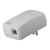
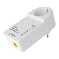
LED Definitions
(Buttons from top to bottom)
1. VPI
Displays the quality of the powerline link when the adapter is synchronized with
another adapter on the same network.
2. ETH
Displays the presence of an Ethernet link and activity on the link.
Blinking: receiving/transmitting data
Connector Definitions
(Connectors from left to right)
1. LAN: 1x RJ-45 LAN10/100 Ethernet port
7
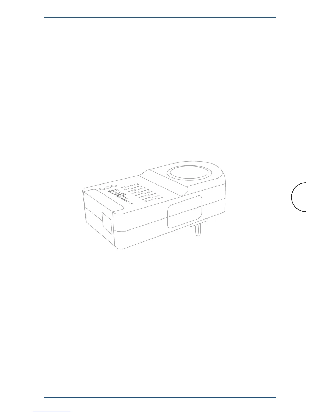
Installation
Corinex AV200 Powerline Ethernet Wall Mount F
2.4 Functional Description
2.4.1 Standby Button
By default, when plugged in, the adapter is in the ON state. When Standby operation
is desired, the button should be pressed and released at once. This will set the
adapter in energy-saving Standby operation mode. When the adapter is in Standby
operation, the button can be pressed to set the adapter back into the ON mode.
2.4.2 SYNC/ RST Buttton
2.4.2.1 One-button Security Setup (OBUS)
By default, powerline adapters come without a network identifier and without an
encryption key. As a result, when they are plugged in, a new Powerline network will
be created (referred to as a public network).