Countertop Icemaker IMD Series Installation Manual
Publication Number: 638085277INS - 6 - © 2004-2012, IMI Cornelius Inc.
ELECTRICAL SUPPLY
1. Power Access - Is provided by way of a 7/8” dia. hole in both the base and the rear panel. Route incoming
power in conduit, to icemaker electrical control box. Make connections to wires provided in control box and
ground lug/screw. Plug unused hole.
For IMD600-30A and IMD300-30A units, 8 feet, 2 inch long power cord with 3 prong plug attached to the unit.
2. Fu
sed Line - Should be a dedicated circuit checked and sized according to electrical rating shown on unit
nameplate.
NOTE: Unit must be installed per local electrical code.
DRAIN CONNECTION
1. Install splash panel on machine and hold in place with (2) screws. Do not tighten at this time.
2. Remove drain tray mounting bracket from their shipping carton.
3. Clip the drain try mounting bracket
onto the bottom of the splash panel in the brackets provided.
4. Hook the drain tray into the splash panel and onto the mounting bracket.
5. Push the drain elbow securely onto the drain tray. Do not glue in place.
6. Complete drain hookup according to the instructions provided with unit.
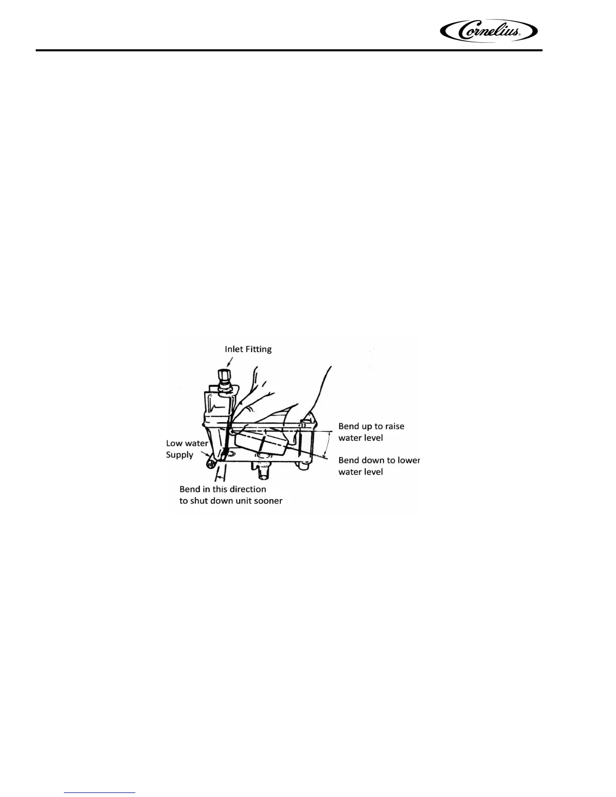
Figure 4. Float Assembly
NOTE: Steps 7 and 8 to be completed only after all start up checks and adjustments are performed.
7. Replace side panels tightening all (6) screws (including splash panel screws left loose).
8. Replace top panel and front cover and secure with (2) screws.
NOTE: In those cases where the unit is base mounted and not on legs it should be sealed all
a
round the base with NSF listed sealant. (IMI Wilshire P/N 04815-B).



 To Next Page