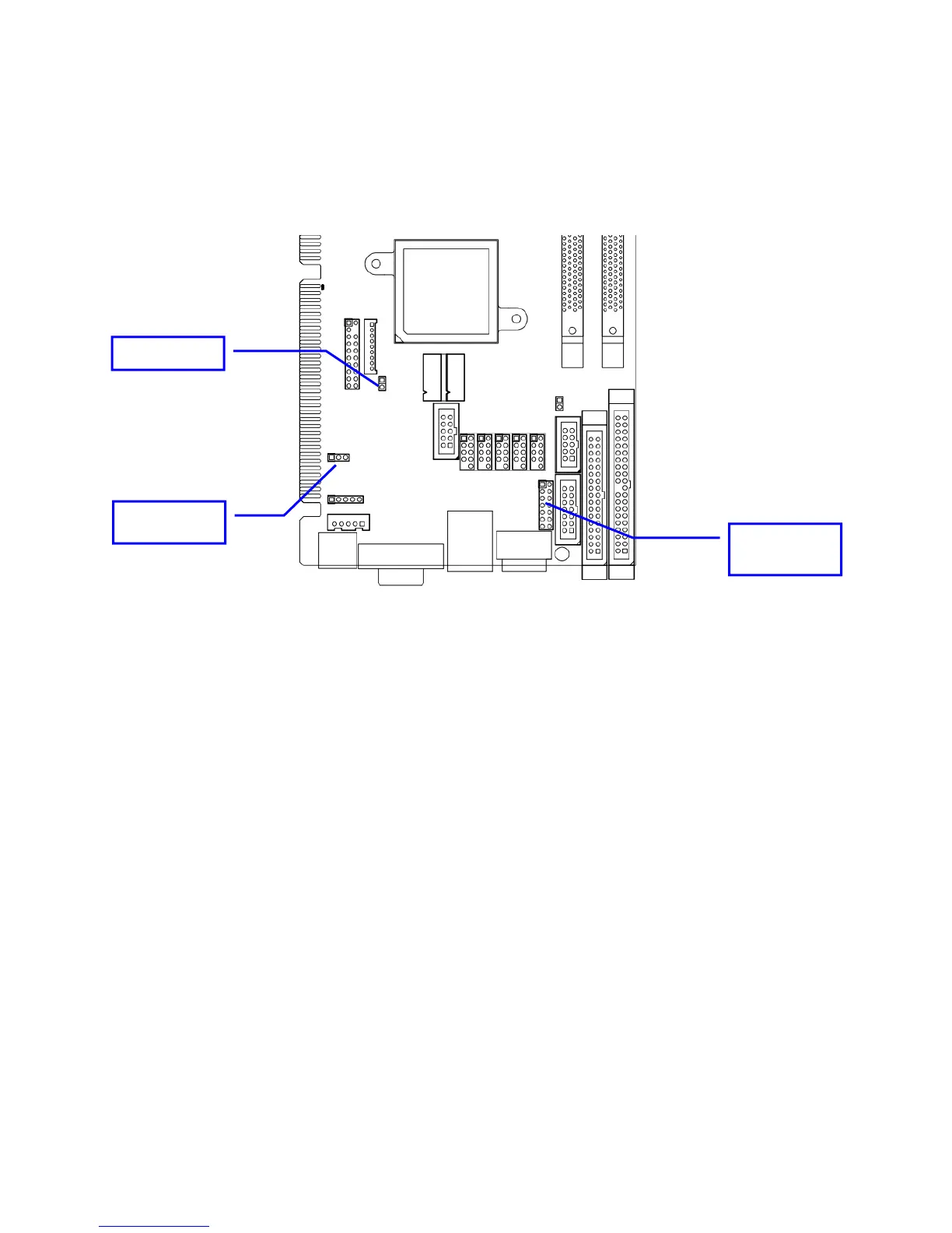
Jumper Location
Use the diagram below and the tables on the following pages to locate and set the on-board
configuration jumpers.
CMOS
(JBAT1)
COM2 MODE
(JRS1))
AT/ATX (AT1)
AT1 – AT/ATX Power Mode
This option allows the selection of the power type. Default is ATX (open).
CMOS Reset: JBAT1
This option is provided as a convenience for those who need to reset the CMOS registers. It should
always be set to “Normal” (1-2) for standard operation. If the CMOS needs to be reset, turn off the
system; move JBAT1 to 2-3, and back to 1-2, and power the system on.
PATA IDE Enable/Disable: JP1
This option enables/disables the PATA controller. Default is enabled (open)
16