Installation 8
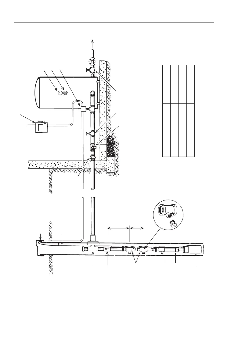
Pitless
Check
valve
e
Pipe
coupling
Tape cable
to pipe
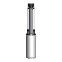
Pump
Ventilated well cap
Submersible cable
Union
Pressure gauge
Air volume contro
Pressure switch
To house
service
Gate valve
Relief valve
2 ft.
(.6 m)
See table
Figure 11 – Typical Standard Tank Installation
Check Valve Distance to Top Bleeder Orifice
Tank Size - Gallon (L) Distance Ft. (m)
42 (159) 2 (.6)
82 (310.4) 3 (.9)
120 (454.2) 5 (1.5)
NOTICE 2-Wire motors do not use a control box. Run motor
wire from pressure switch directly to motor.
See Cabling for detailed wiring instructions.