Installation 9
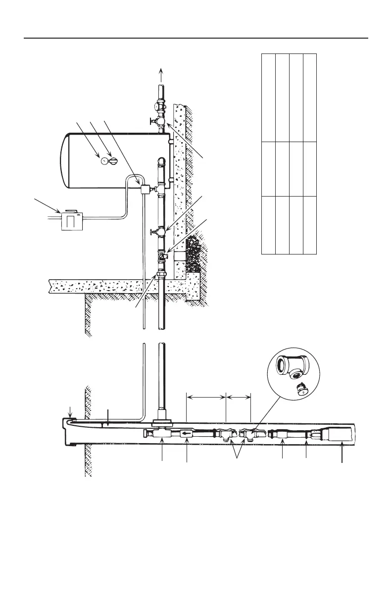
Pitless
Check
valve
e
Pipe
coupling
Tape cable
to pipe
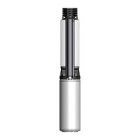
Pump
Ventilated well cap
Submersible cable
Union
Pressure gauge
Air volume contro
Pressure switch
To house
service
Gate valve
Relief valve
2 ft.
(.6 m)
See table
Figure 12 – Typical Pre-Charge Tank Installation
Cut-In PSI Cut-Off PSI Pre-charge Pressure
20 (138 kPa) 40 (276 kPa) 18 PSI (124 kPa)
30 (207 kPa) 50 (345 kPa) 28 PSI (193 kPa)
40 (276 kPa) 60 (414 kPa) 38 PSI (262 kPa)
NOTICE 2-Wire motors do not use a control box. Run motor
wire from pressure switch directly to motor.
See Cabling for detailed wiring instructions.