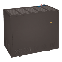
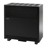
COUNTERFLOW DIRECT VENT GAS WALL HEATER 23
FURNACE TECHNICAL INFORMATION
MODEL
NUMBER
GAS TPE
INPUT**
RATING
BTU/hr.
MAIN BURNER ORIFICE
DRILL DEC. QTY.
DVCF402D NATURAL 40,000 #32 .1160 1
DVCF401D PROPANE 40,000 #48 .0760 1
DVCF602D NATURAL 60,000 #38 .1010 2
DVCF601D PROPANE 60,000 N/A .0640 2
GAS CONVERSION KITS
NATURAL GAS TO PROPANE GAS
MODEL DESCRIPTION
7728 DVCF40XD
7732 DVCF60XD
GAS CONVERSION KITS
PROPANE NATURAL GAS
MODEL DESCRIPTION
7729 DVCF40XD
7733 DVCF60XD
BURNER CLEANING
Check burner. If cleaning is required, contact a qualified
service technician to clean and service burner.
WARNING: Danger of bodily injury or death.
Make sure electric power and gas supply are off before
removing panels or doors, etc.
CLEANING BURNER COMPARTMENT
Because cold air is attracted to the flame during furnace
operation, a build up of lint from bedding and dust, etc.,
in the burner area will occur each heating season. It is
necessary to clean this area regularly. Use a vacuum
cleaner with a narrow attachment to reach small areas. Be
careful in and around the pilot. A change in its adjustment
could be made if struck during cleaning.
WARNING: A BUILDUP OF ANY DUST, LINT
OR FOREIGN MATERIAL IN THE PRIMARY AIR
OPENING OF THE BURNER CAN INTERFERE WITH
THE PROPER AIR GAS MIXTURE AND GAN RESULT
IN A YELLOW FLAME WHICH CAN PRODUCE
CARBON MONOXIDE AND SOOT. THIS CONDITION,
IF ALLOWED TO DEVELOP, CAN LEAD TO BODILY
INJURY INCLUDING DEATH. IT IS IMPERATIVE THAT
THE BURNER(S) BE KEPT GLEAN.
Disconnect the gas line inside the cabinet.
Remove three screws from the front of the combustion
chamber bottom panel and drop the assembly down.
Clean inside the combustion chamber and the burner
with a shop type vacuum cleaner.
To remove burners remove screw from the end of the
burner and slide the burner out of its bracket (it may be
necessary to slightly spring the bracket).
Inspect the Burner Box gasket. Replace if damaged.
Replace burner assembly and control assembly by
reversing the above procedures.
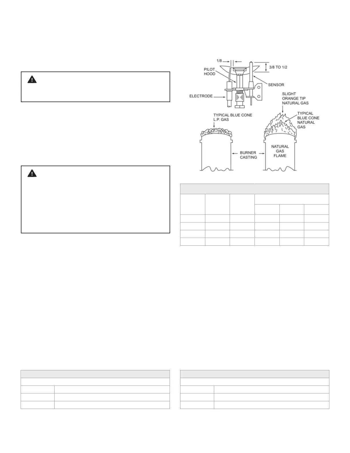
Check the spark gap. It must be carefully adjusted to
specifications, as illustrated (Figure 30), for the ignition
device to function properly.
FIGURE 30 - PILOT FLAME & SPARK GAP
The efficiency rating of these appliances is a product of
a thermal efficiency rating system determined under
continuous operating conditions and was determined
independently of any installed system.
**For elevations above 2,000 feet reduce ratings 4% for
each 1,000 feet above sea level.
**BTU/hr. = British Thermal Units per hour.
PROPANE
GAS
FLAME