Page 15
31300-A:CABINETTRIMKIT
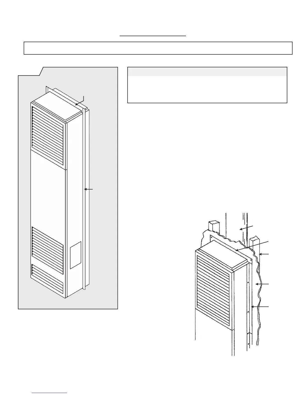
FIG. 12-A
UnitswithTerminalBoard
1. Install top ange and secure with two (2) screws.
2. Select one of the remaining side anges and position as shown in
Figure 12-B (below), making sure that the side with holes is held against
the side of the furnace (and that the ange is ush with the bottom of the
top trim piece).
Mark these holes and removed side ange. Drill the marked holes with No.
30 drill bit. Re-position ange and secure with screws provided.
3. Measure from the bottom of the side ange you have just installed to the
oor. Cut one of the remaining side anges to the measurement and install
as in step 2.
Repeat steps 2 and 3 for opposite side of furnace.
48” Long Side Flange ............................ Qty. 4 31310
15-1/2” Wide Top Flange .......................... Qty. 1 31320
#8 Phillips Head Screws ......................... Qty. 10 50134
TOP
FLANGE
LONG
SIDE
FLANGE
FIG. 12-B
Wall
Trim Kit
Side
Flange
Wall
Stud
Vent
Pipe
FURNACE
Trim
Kit Top
Flange
CAUTION: These kits must be installed by a qualified installer or service technician.
PART DESCRIPTION PARTNO.QUANTITY


 To Next Page