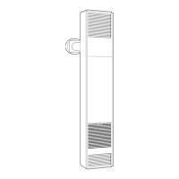
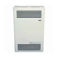
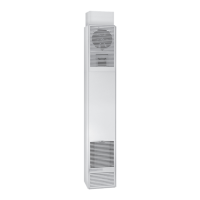
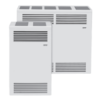
DIRECT VENT
COUNTERFLOW
WALL FURNACE
Installation and
Operating Instructions
ENGLISH
Click here for the full manual or
click on the links below to quickly
locate what you’re looking for:
ESPAÑOL
Haga clic aquí para ver el manual
completo o haga clic en los
siguientes enlaces para localizar
rápidamente lo que está buscando:
FRANÇAIS
Cliquez ici pour le manuel complet
ou cliquez sur les liens ci-dessous
pour localiser rapidement ce que
vous recherchez:
1018028-A_webcvr
Antes de la Instalación
Estándares
.......................................... 2
Especicaciones y Dimensiones
......... 3
Introducción
........................................ 3
Reglas de Seguridad
...................... 3 - 4
Desfogue
............................................. 4
Espacios Libres
.............................. 5 - 6
Ubicaciones
......................................... 7
Instalación
Instrucciones Generales
................. 7 - 8
Ubicar abertura de Ventilación
............ 8
Conexión de Gas
................................. 8
Instalación del Termostato
................... 8
Instrucciones de Encendido
......... 9 - 10
Mantenimiento
Instrucciones de mantenimiento
........ 11
Ajuste piloto
....................................... 11
Eliminación de quemadores
.............. 12
Gráco de llamas
y oricios del quemador ..................... 12
Diagramas de cableado .............. 12 - 13
Kits:
14-PEK
Kit de extensión
............................. 14
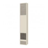
31300-A
Kit de acabado de gabinete
.......... 15
306SR-A y 30SRB-A
Kits de descarga lateral
................ 16
Cuadros de solución
de problemas
.............................. 17 - 19
Lista de Piezas
........................... 20 - 23
Garantía ............................................. 24
Avant l’installation
Normes
................................................ 2
Spécications et dimensions
............... 3
Introduction
.......................................... 3
Règles de sécurité
.......................... 3 - 4
Desfogue
............................................. 4
Espace libre
.................................... 5 - 6
Emplacements
..................................... 7
Installation
Instructions générales
.................... 7 - 8
Localiser l’ouverture de ventilation
...... 8
Raccordement au gaz
......................... 8
Installation du thermostat
.................... 8
Instructions d’allumage
................. 9 - 10
Maintenance
Instructions de maintenance .............. 11
Réglage du pilote ............................... 11
Élimination des brûleurs
.................... 12
Tableau de amme
et les trous du brûleur
........................ 12
Schémas de câblage
.................. 12 - 13
Kits:
14-PEK
Kit d’extension
.............................. 14
31300-A
Kit de nition de l’armoire
............. 15
306SR-A et 30SRB-A
Kits de déchargement latéral
........ 16
Tables de solution
des problèmes
............................ 17 - 19
DVCF Liste des pièces
............... 20 - 23
Garantie
............................................. 24
Before Installation
Standards
............................................ 2
Specications
...................................... 3
Introduction
......................................... 3
Venting ................................................. 4
Safety
............................................. 3 - 4
Clearances
..................................... 5 - 6
Locations
............................................. 7
Installation
Rough-In Instructions
..................... 7 - 8
Locate Vent Opening
........................... 8
Gas Connection
................................... 8
Thermostat Installation
........................ 8
Lighting Instructions ...................... 9 - 10
Maintenance
Maintenance Instructions ................... 11
Pilot Adjustment
................................. 11
Burner Removal ................................. 12
Burner Flame
& Orice Chart
................................... 12
Wiring Diagrams
......................... 12 - 13
Kits:
14-PEK
Extension Kit
................................. 14
31300-A
Cabinet Trim Kit
........................... 15
306SR-A & 30SRB-A:
Side Discharge Kits
..................... 16
Troubleshooting Charts
.............. 17 - 19
DVCF Part List ............................ 20 - 23
Warranty
............................................ 24